Insert Molding Design Rules for Metal-to-Plastic Interface Strength
Mechanical geometry, not adhesive, determines insert retention strength.
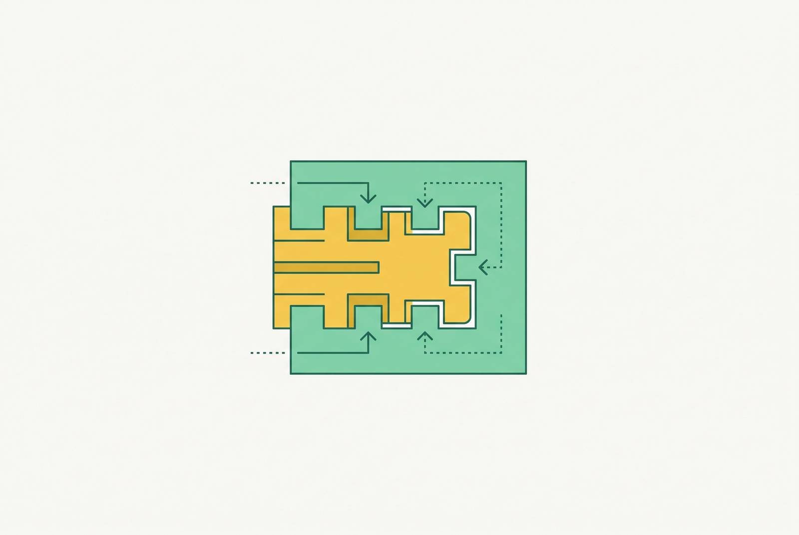
Insert molding interface strength comes mainly from mechanical geometry. Strong designs give the resin features to lock into, enough surrounding material to resist stress, and a filling path that leaves no gaps. The design task is to resist pull-out and rotation without creating cracking or sink during cooling and service.
Why insert molding failures are a geometry problem, not a bonding problem
An insert pulls out under load, spins under torque, or cracks the boss around it after thermal cycling. The metal may still look sound. The failure is at the interface, where the plastic either lacks a mechanical lock or cannot withstand the stress around it. Treating that interface as an adhesive joint leads to the wrong design decisions.
ZetarMold's design guide states that mechanical retention from knurls, grooves, and undercuts dominates bond strength, while any adhesive contribution is secondary. In insert molding, plastic flows around the metal and solidifies around its retention features. Those features give the joint its grip. A smooth cylindrical insert instead depends on surface adhesion, which degrades under vibration, cyclic loading, and thermal expansion.
The design therefore has to address distinct loads rather than an undefined requirement for “good bonding.” Pull-out is an axial failure, while rotation is a torsional failure. Cracking comes from stress in the surrounding resin, including hoop stress around the insert. Sink is a wall-geometry defect tied to shrinkage. A feature that solves one of these problems does not automatically solve the others.
How mechanical retention features work and which failure mode each one resists
Circumferential undercut grooves primarily resist axial pull-out. Once the resin solidifies, it forms a mechanical key inside the groove that keeps the insert from sliding straight out. Rotation is a separate design problem, however. A circular groove does not significantly resist turning on its own, so specifying groove depth without considering torque leaves part of the retention requirement unresolved.
Hex or polygonal cross-sections directly resist rotation. Combined with a groove, they address both twisting and axial withdrawal. Diamond or straight knurling creates interlocking teeth that the plastic flows into under injection pressure, increasing surface contact and resisting pull-out and rotation. Even so, the design must account for each load on its own. A knurl specification alone is not proof that the finished part meets either requirement.
A molded-in insert with knurling and an undercut groove typically withstands significantly more pull-out load than a smooth insert because resin fills the retention features under pressure. Sharp corners on the insert concentrate stress in the surrounding resin and can initiate interface cracking, so insert geometry should have no sharp edges. The insert must also protrude at least 0.4 mm into the mold cavity, with the supporting plastic depth governed by the boss dimensions discussed below.
How CTE mismatch between the insert and the resin determines long-term interface stress
The coefficient of thermal expansion, or CTE, describes how much a material expands with temperature. When the metal and resin expand by different amounts, they put cyclic stress on the interface. If that stress exceeds the interface strength, cracking or pull-out can follow despite correctly designed retention features.
A brass/nylon pairing should not become the default simply because it is convenient. Stainless 304 has a CTE of ~17.3 × 10⁻⁶/°C and pairs better with PPE, PPS, and LCP. Carbon steel, with a CTE of ~12.0 × 10⁻⁶/°C, presents a large mismatch and requires either flexible polymers or designed compliance features in the boss geometry.
Glass- and mineral-reinforced resins have lower mold shrinkage than their base resins, reducing hoop stress. DuPont's General Design Principles for Engineering Polymers notes that weld lines in heavily loaded glass-filled material may have only 60% of the base material's strength. A rib at that location substantially increases support. Lower shrinkage does not remove the need to account for a weak weld line.
For a quick design check, strain in the material around the insert is approximately equal to mold shrinkage, giving stress ≈ shrinkage × flexural modulus. This estimate helps check wall thickness before it is set, but simulation is still needed. Preheating inserts reduces the temperature difference between molten plastic and cold metal, limiting residual stress and premature freeze-off that would create a weak bond line. This is especially important with high-shrink materials.
Boss wall thickness rules that prevent cracking, sink, and uneven shrinkage
Boss wall thickness is where the thermal and mechanical requirements meet. With too little material, hoop stress can cause cracking. Too much risks sink and uneven shrinkage, so adding plastic is not a reliable cure for a weak interface. SWCPU's insert molding design guide identifies sink marks and cracking from shrinkage stress among the common defects traceable to wall geometry.
The starting rule is a boss diameter of at least 1.5 times the insert diameter. For inserts larger than 12.9 mm in diameter, the boss wall must instead be derived from the overall part thickness and the specific material grade. Beneath the insert, the depth of molding must equal at least one-sixth of the insert's diameter. If the depth is too small, sink marks form on the opposite outer surface.
The wall must also be uniform around the circumference. A thin side opposite a thick side cools and shrinks unevenly, creating asymmetric stress and increasing cracking risk. Making the wall thicker can itself increase mold shrinkage and hoop stress in a nonlinear relationship, so walls that are too thick are especially risky in high-shrink materials. Abrupt thickness changes near the boss add stress concentration. Fillets and gradual transitions distribute the load without relying on a larger mass of plastic.
Gate placement and injection parameters that protect insert position and fill quality
Correct geometry only works if the resin fills it and the insert stays in position. Gate placement should be part of the design-for-manufacturing review before the tooling is agreed on. Gates should be away from thin sections adjacent to inserts because flow directed at those sections can displace the metal before the plastic freezes around it.
High-viscosity resins need higher injection pressure, so it is especially important to keep the insert restrained. An insert must be positively retained through mold close and the start of injection. The mold design should therefore include a defined locating approach, such as spring-loaded pins, magnetic pockets, or tapered seats. Locating-surface tolerances belong in the same discussion.
Packing pressure and packing time are more critical here than in standard molding because the plastic must remain under pressure long enough to compensate for volumetric shrinkage around the insert. Insufficient packing produces outer-surface sink and interface voids. When flow around the insert is balanced, it helps prevent weld lines and air traps, while proper venting lets trapped air out from between metal and plastic. A void in a knurl groove gives no retention. The DFM conversation should address gate location, flow balance, venting, and restraint together rather than assuming a well-drawn knurl will fill properly.
When to specify molded-in inserts versus post-mold installation methods
Specify molded-in inserts when production is committed, retention specifications are firm, and the strongest mechanical lock is required. Injection pressure drives resin into the knurls and undercuts and around the insert geometry. That is the decisive retention advantage. ZetarMold's guide also identifies high torque resistance and hermetic sealing in a single cycle as conditions where insert molding beats ultrasonic welding and press-fitting.
For prototypes and early iterations, the decision changes. Heat staking and ultrasonic insertion preserve flexibility when insert size or location may change, without committing to a mold modification. Secondary insertion may also be more practical for low-volume or frequently changing designs. Its retention limit is lower, however. Pull-out and torque-out testing must establish whether that limit still meets the application's requirements.
Tooling cost is a real constraint that must be weighed alongside retention requirements. Undercuts that require side actions, lifters, or collapsible cores add tooling cost and extend lead time. The DFM objective is to eliminate unnecessary undercuts early and review any required side-action concept before mold design is locked. The choice follows the load requirement and production commitment. Post-mold installation is appropriate when its validated strength is sufficient and flexibility is valuable, rather than as a habitual substitute for molded-in retention.
Surface preparation, insert cleanliness, and the QA checks that catch interface failures early
Oil, wax, and machining residue act as release agents and prevent plastic from filling the knurl geometry properly. Cleanliness is part of the interface specification. Inserts must be clean, dry, and free of machining oils or other surface contaminants before placement, with ultrasonic cleaning or a solvent dip followed by hot-air drying among the preparation methods used.
The engineering handoff should make those requirements explicit. For customer-supplied inserts, the package should also include orientation marks and plating notes. Acceptance must be based on physical pull-out force and torque-out testing against specified values. Resin choice changes the result. A knurl geometry that meets the requirement in one resin may fail in a lower-modulus material.
Qualification should include sectioning an insert-molded part and examining the cut face under magnification. This destructive check reveals interface voids, incomplete filling of knurl grooves, and outer-surface sink. It is standard during initial process qualification and after any tool modification. Retention testing then establishes whether the finished interface withstands the specified loads.
Production monitoring must also stay tied to the interface. In-process statistical process control should track cycle time consistency, cushion position, and peak injection pressure. Deviations from established process windows correlate directly with insert displacement and packing defects. Cleaning requirements cover the surface as it arrives, while process monitoring catches drift that can cause even correctly shaped parts to fail during molding.
How to structure the file package and DFM conversation to avoid losing time before tooling
A complete CAD-to-quote package gives the supplier what it needs to check the interface before tool design begins. It should include plastic part CAD, insert CAD or drawings, resin preference, insert material specification, quantities, cosmetic class, and pull-out and torque acceptance specifications. Reference photos of a competitor or predecessor part help when drawings are incomplete. The load requirements belong with the geometry. Without them, a drawing shows the joint but leaves out how well it must perform.
Before tooling is cut, the DFM review must resolve undercut direction and the side-action concept, gate location relative to inserts, boss wall thickness, the insert locating approach, and tolerances on locating surfaces. These decisions connect the retention design to a mold that can produce it. The buyer also has control over when the review takes place. A review that should take a few days when changes are reviewed in real time can stretch to 10 days when changes wait for weekly engineering meetings.
In an insert molding program, more calendar time is lost during DFM review than during tool build. Mold build time is set by complexity, while review time varies with the completeness of the package and the speed of decisions. Splitting the BOM adds another source of delay. Buying plastic molding from one vendor, inserts from another, and assembly from a third creates interfaces where dimensional mismatches accumulate and schedule dependencies multiply. The sourcing package should therefore keep the insert, molded boss, assembly requirements, and acceptance criteria connected.