Laser Cutting Kerf and Heat-Affected Zone Effects on Tight-Tolerance Features
Kerf and heat-affected zone shift independently and demand separate control strategies in design.
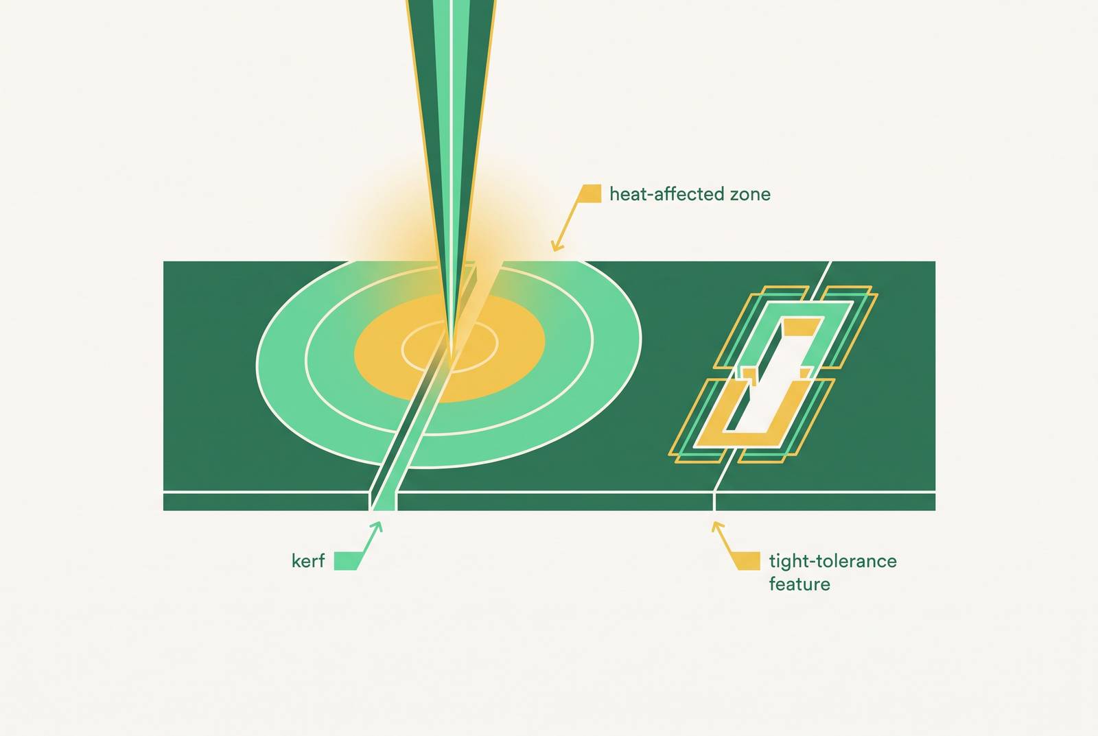
Kerf and heat-affected zone are outputs. Material, thickness, and the parameters running that day shape them, and they move independently of each other even though the same beam causes both. Engineers who treat them as design variables, not machine specs, catch tolerance problems on paper instead of at final inspection, when the parts are already sitting in a bin marked "hold."
Start with definitions, because the two terms get mixed up constantly. Kerf is the channel of material the beam removes, measured edge to edge across the cut. That's not the same thing as beam width, which only describes the focused spot diameter before it ever touches metal. HAZ, heat-affected zone, is the band of base material next to that cut that never left the part but got cooked anyway. Its grain structure changed from the heat, even though nothing got removed. Kerf and HAZ sit right next to each other on a cut edge, but they behave differently, and managing one does nothing to manage the other.
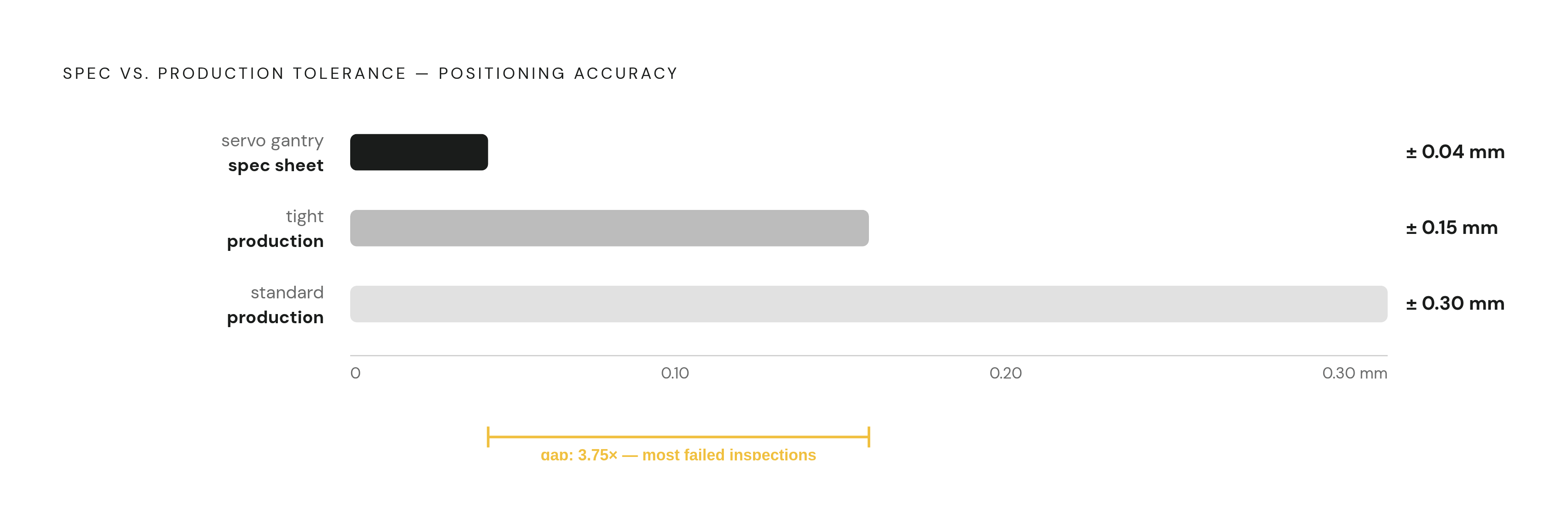
Positioning accuracy gets mistaken for cutting accuracy before the part ever hits the machine, and that mix-up is where a lot of tolerance stack-ups start. A servo-driven gantry might hold ±0.04 mm positioning, and that number shows up on the spec sheet, so people treat it as the tolerance the finished part will hit. Wrong move: positioning accuracy describes where the cutting head goes, and says nothing about what the finished edge looks like once kerf width, taper, and thermal drift get added on top. Real production tolerance on typical stock runs ±0.15 mm to ±0.3 mm, not ±0.04 mm, and the gap between those two numbers is where most failed inspections come from.
Kerf width shifts by laser source, material, and thickness
Across all laser cutting, kerf runs anywhere from 0.08 mm to 1 mm. That's a wide spread, and the exact number depends on the laser source, the material, the thickness, and how well the machine's dialed in that day. Nothing about kerf is a constant you look up once and reuse on the next job.
Fiber and CO₂ lasers land in different bands. Fiber typically runs 0.15 to 0.5 mm overall, and on thin sheet (0.5 to 3 mm steel or stainless) it tightens up to 0.10 to 0.25 mm. CO₂ runs wider, typically 0.25 to 0.5 mm, and on 2 mm mild steel specifically, expect 0.30 to 0.45 mm. Same job, same power level: fiber gives 0.15 to 0.25 mm, CO₂ gives 0.30 to 0.45 mm. That gap is big enough to make a press-fit tab seat clean or jam halfway in.
Material matters just as much as laser type. On a fiber laser running good parameters, carbon steel comes in narrowest at 0.1 to 0.25 mm. Stainless sits close behind at 0.12 to 0.25 mm. Aluminum and copper run wider, 0.15 to 0.35 mm, due to their thermal properties.
Kerf isn't a clean, parallel-sided slot cut straight through the plate, either. It tapers: wider at the top surface where the beam enters, narrower at the bottom where it exits. On thin sheet that taper only adds up to 0.02 to 0.05 mm, small enough to ignore on most jobs. On thick plate the taper grows, and it starts to matter a lot for through-holes and press-fit pins that need to seat flush the whole way through, not just at the entry face.
Why focus drift erodes tolerance faster than any other variable
Normal kerf variation, the ranges above, is something a shop plans around. Focus drift is a different animal. It changes the physics of the cut itself, before assist gas ever gets a chance to clear the melt.
When focus drifts off the cut plane, the beam's energy spreads across a wider area instead of concentrating into a tight spot, so energy density in the cut zone drops. A kerf that was running a clean 0.2 mm can swell to 0.4 mm, seemingly out of nowhere. Once the melt pool gets that wide, assist gas can't clear it efficiently anymore, even with line pressure unchanged. The gas is doing the same job it always did. The melt pool just got too big for it to do that job well.
Thermal expansion during long production runs causes exactly this kind of drift. Cutting a dense nesting layout across a full sheet pumps heat into the metal steadily, and the sheet's coordinate system warps underneath the gantry as it heats up. The machine keeps positioning to its spec the entire time. It has no way of knowing the steel underneath it has physically moved.
So on any job with a tight tolerance riding on it, verifying actual production variation across the sheet, not just relying on the number printed on the machine's spec sheet, is what reveals the real tolerance for that job, on that sheet, that day.
What HAZ does to material at the cut edge, and why it matters by alloy
Laser cutting produces a HAZ of roughly 0.1 to 0.3 mm. Manual TIG welding, for comparison, leaves a HAZ of 1.5 to 2.4 mm or more. But narrow isn't the same as zero, and 0.1 to 0.3 mm of altered microstructure sitting right at a cut edge is plenty to throw off a tight-tolerance feature.
HAZ width tracks the same power-and-speed relationship kerf does. It grows with laser power and shrinks as cutting speed goes up, a relationship consistent with published research on laser-cut edge quality. Same drivers, different response, and that's exactly why kerf and HAZ have to get managed as two separate variables instead of one lumped-together "heat effect."
The alloy changes how that heat actually shows up. S355J2 structural steel produces relatively low surface roughness but the most pronounced surface hardening, with maximum microhardness reaching about 700 HV 0.1 packed into a fairly narrow HAZ. AISI 304 stainless shows a distinct edge-hardening effect too, though with more moderate roughness than S355J2. AlMg3 aluminum tells a different story entirely: a visibly remelted layer forms at the edge, with a refined, fine-grained microstructure underneath. Hardness stays lower overall, but the HAZ itself spreads out rather than staying sharply bounded.
The mechanism comes down to what each alloy does under rapid heating and cooling. Carbon steel forms martensite right at the cut edge, which raises hardness but also brittleness. Chromium carbides can precipitate out of stainless steel at the edge, weakening corrosion resistance right where the part is most exposed, a real problem for anything headed into wet or corrosive service. Aluminum alloys often go the other way: localized heating lowers hardness rather than raising it, especially in heat-treatable grades where the temper condition itself gets altered by the heat.
When HAZ becomes a forming and assembly failure mode
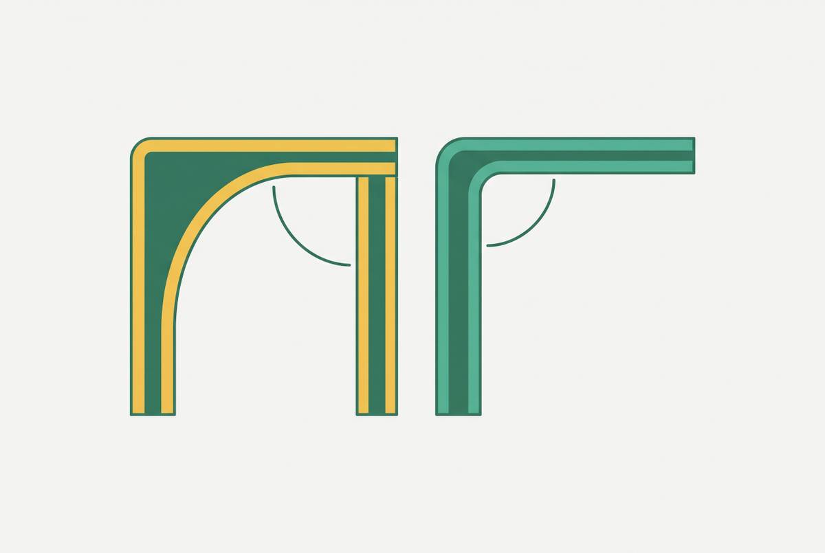
A laser-cut edge with altered hardness, or reduced ductility from martensite formation, cracks during a tight bend. That's the direct result of forming a hardened, brittle zone at exactly the spot where bending strain runs highest, which happens whenever the bend line sits right along a cut edge.
Two fixes exist, and picking wrong costs a redesign later. One: add extra stock and machine the edge after laser cutting, removing the HAZ before the part ever gets formed. Two: move the bend line away from the cut edge entirely, so the HAZ sits outside the zone of maximum strain. Which one makes sense depends on part geometry and what the tolerance budget can absorb.
For sealing surfaces and precision-fit assemblies, ISO 9013:2017 gives a way to put this requirement directly on the drawing. Range 1 is the tightest edge quality class under that standard, and it's the one that supports sealing surfaces and precision fits. Range 3 is looser, fine for parts headed to powder coat or weld prep where edge condition carries no functional load. Calling out the right range tells the shop what actually matters, without forcing every dimension on the part into a tolerance tighter than it needs.
Waterjet cutting avoids heat-affected zones entirely rather than just shrinking them. No heat means no HAZ and no altered microstructure at the edge, full stop. Where a part is prone to thermal distortion, needs a stable microstructure right at the cut line, or uses a heat-sensitive temper that can't take any localized heating, waterjet is the right call, not laser, even if it costs more per part.
Tolerance regimes by thickness and what "tight" means in production
Across the industry, laser cutting reliably holds tolerances between ±0.05 mm and ±0.3 mm, and where a given job lands in that range depends on material, thickness, and machine type. No single number applies across every job, every sheet, every alloy, so treat any spec sheet claiming otherwise with suspicion.
3 mm thickness marks a real threshold. Below it, a tolerance of 0.1 mm counts as tight for most production shops, achievable reliably on a calibrated fiber laser running nitrogen assist gas. Past 3 mm, the tolerance budget has to open up, because both kerf width and HAZ grow with thickness, leaving less room to hold a tight number without cost climbing fast.
And that cost climbs faster than most people expect. Tightening a tolerance doesn't add cost in a straight line, it curves sharply upward. Ultra-precision tolerances, on the order of ±0.001 in., can run four to five times the cost of a standard tolerance job, and that penalty gets steeper still as thickness increases, because holding a tight number on thick plate demands far more process control than holding it on thin sheet.
Save the tight tolerances, the 0.1 mm and 0.05 mm calls, for features that carry an actual functional requirement: fits, sealing surfaces, bearing bores. Let everything else on the part run looser. That's correct engineering, a part that costs what it should instead of one that costs four times more for tolerances nobody downstream will ever use.
Kerf compensation responsibilities in CAD and DXF files
Under normal conditions, kerf compensation is the shop's job, not the designer's. Parts get modeled at nominal size, and the CAM software offsets the toolpath by half the kerf width so the finished part is the dimension on the drawing. That's the standard workflow, and it works fine for the overwhelming majority of features on a part.
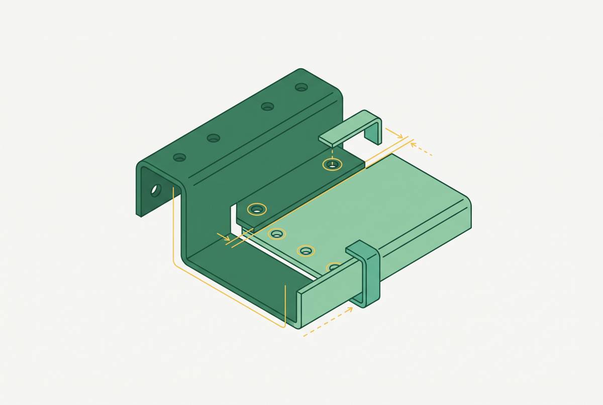
It breaks down for tab-and-slot joints, press-fit features, and any geometry where two laser-cut surfaces need to mate directly. The shop's nominal-offset approach assumes one cut edge and one finished dimension. Tab-and-slot geometry has two mating surfaces, both losing material to kerf, and a single toolpath offset can't account for both sides of that fit at once. Here the engineer has to step in and compensate directly in the DXF file, because the shop has no way to guess the intended fit from a nominal drawing alone.
The rule for press fits is straightforward. Draw tabs 0.1 mm wider than the target assembled gap. Draw slots 0.1 mm narrower than that same gap. The result is a controlled interference fit: snug enough to hold without a fastener, but with enough give that it won't crack the material going in.
Internal corners complicate tab-and-slot fits further, because the beam itself can't cut a perfectly sharp inside corner. It leaves a small radius there, a direct result of the beam's own geometry, so a square tab won't seat fully into a square slot without hitting that radius first. Fix it by lengthening the tab slightly so it clears the rounded corner, or by adding a dog-bone relief cut into the slot's corners, giving the tab's square edge somewhere to go.
DFM rules for holes, slots, edge distances, and internal corners
Hole diameter and material thickness need to track together. A hole cut smaller than the sheet is thick starts to taper noticeably from kerf angle and struggles to hold a round profile, so keep minimum hole diameter at or above material thickness as a working rule. Below that ratio, roundness and wall straightness get unreliable fast.
Slots follow the same logic, but the constraint runs along the narrow dimension. A slot narrower than the kerf width risks closing in on itself, or coming out ragged where the two cut walls sit too close for the melt to clear cleanly.
Edge distance, the gap between a cut feature and the part's outer edge, needs enough margin to keep the HAZ from a nearby cut edge from overlapping the feature being held to tolerance. A tight hole placed right next to an outer edge sits inside two heat-affected zones at once, one from each cut, and that stacks the risk of distortion right where the part can least afford it.
Internal corners always carry some radius from the beam, never a true sharp point, so design for that up front. Specify a small fillet where a sharp corner isn't functionally required. Plan dog-bone relief where a mating part needs a true square corner. Fighting the physics of the beam on paper costs nothing. Fighting it after the parts come back from the shop costs the whole production run.
Sources
- Laser vs. Water Jet Cutting:How Speed, Kerf & Heat Affect Part Quality
- Sheet Metal Laser Cutting Tolerances: ISO 9013 & DFM
- Laser Cutting Machine Tolerance: Why ±0.1mm Specs Destroy Fit-Ups - ADH Machine Tool
- What Is Laser Cutting Kerf: Width, Calculation and Factors - ACCURL
- Laser Cutting Tolerances: Complete Guide for Engineers
- Laser cutting of various materials: Kerf width size analysis and life cycle assessment of cutting process - ScienceDirect
- Kerf in Laser Cutting: What You Need to Know | MachineMFG
- blog.blmgroup.com