Tolerancing Sheet Metal Parts for Assembly Fit Without Over-Specifying
Match tolerances to each sheet metal process, not to a single blanket number across the drawing.
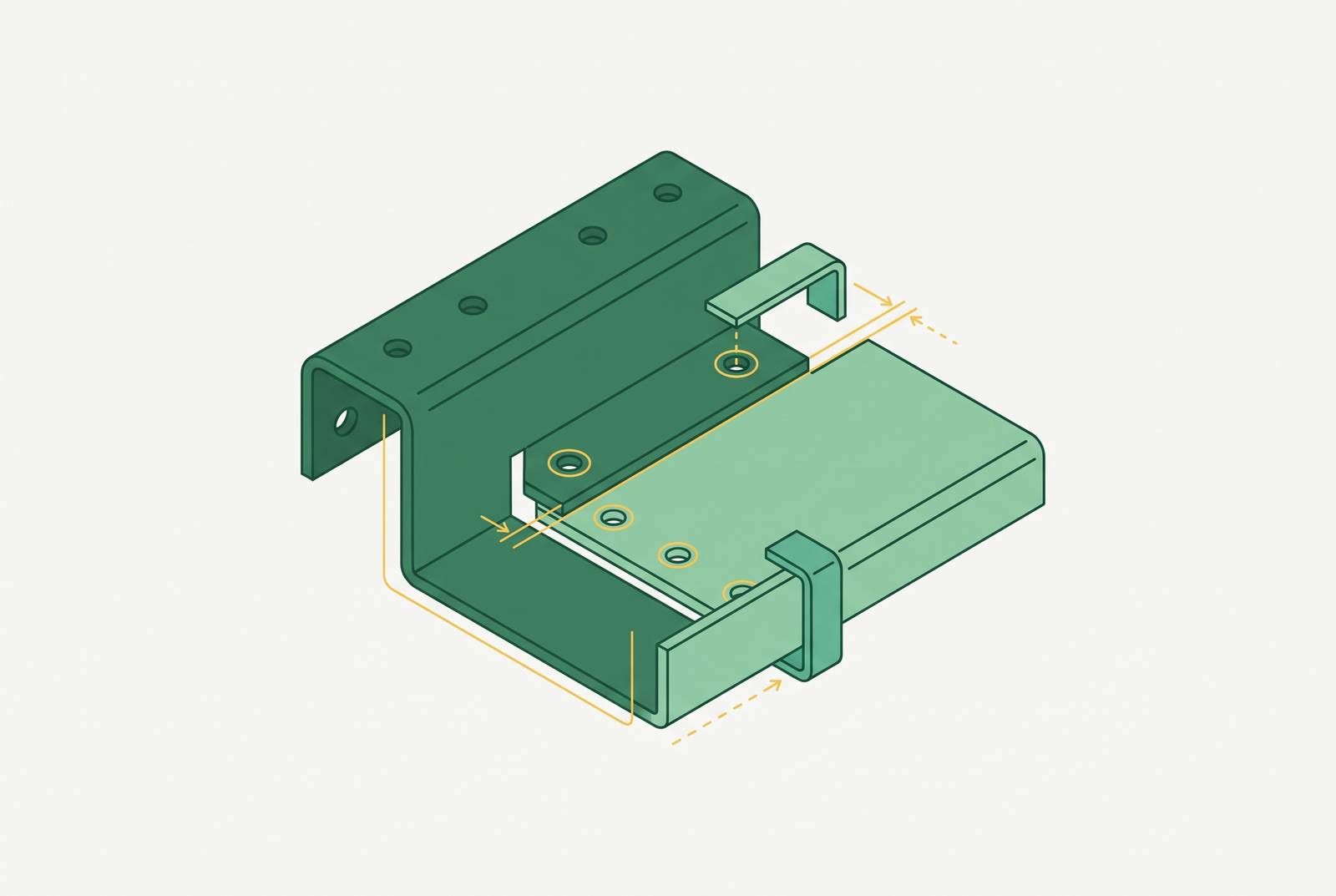
A sheet metal drawing with one blanket tolerance in the title block is telling the fabricator a story that isn't true. Cutting, bending, and forming don't share a single dimensional ceiling, so writing ±0.005" across the board either strangles the budget on features that never needed it or leaves the features that actually matter exposed to failure. The job is matching the callout to the process that makes each feature, not picking one number and hoping it covers everything.
Start with the stock itself. Sheet metal doesn't come from solid billet the way a machined part does. It comes off a coil or a sheet with its own thickness variation baked in, roughly ±0.003" depending on alloy, gauge, and which mill run produced it; Approved Sheet Metal reports this figure. That variation doesn't sit quietly in the material. It travels into every bend made from that sheet. A dimension between two laser-cut holes on a flat face has nothing to do with that variation. A dimension that crosses a bend has everything to do with it. Same drawing, two completely different physics problems, and treating them the same is where the trouble starts.
The cost of ignoring process capability when writing tolerances
Tightening a tolerance past what the process needs isn't caution. It's a cost added for no functional reason at all.
Every step down in tolerance band slows the machine, adds an inspection step, sometimes calls for a dedicated fixture or a climate-controlled room the part never needed before. MakerStage's DFM guidance puts the penalty for moving from a standard tolerance to a close one at 40 to 80% per feature. That's not a rounding error, it separates a profitable run from a quote nobody wants. Fox Valley Metal-Tech has flagged the same pattern one level up, at the assembly stage: unnecessary GD&T, especially the kind that creeps into defense programs, can push manufacturing cost up by 50% or more.
Where does the habit come from? Mostly training. Engineers get taught to apply GD&T broadly, or they tack on a tight callout "just to be safe" instead of asking whether function actually demands it. Nobody gets fired for over-tolerancing. But somebody eventually has to pay for it, and that cost appears as a line item nobody can explain.
Under-specifying has its own bill. Parts that don't assemble generate rework, scrap, and a schedule slip that ripples through the whole program. None of this argues for looser tolerances everywhere. It argues for tolerances that match what the part is actually doing.
A concrete case from EPOC CRAFTER's production data makes the point sharper: a 3 mm hole placed just 1 mm from a bend line in 1.5 mm 5052-H32 aluminum forces a secondary deburring pass, adding 15 to 20% to per-part cost across a 200-piece run. That's a DFM violation more than a tolerance violation, strictly speaking, but the lesson lands the same way. A callout, or a placement, that ignores what the process can actually do generates cost somewhere down the line, whether or not it shows up on the drawing.
MakerStage's fix is not complicated: tighten only where function demands it, add corner radii where the process wants them, get a DFM review before release. That combination typically cuts first-article cost by 20 to 30%.
What each sheet metal process can hold, feature by feature
Start with ISO 2768-m, the medium tolerance class. It's the standard default for commercial and industrial sheet metal work, and it belongs in the title block on every drawing. Explicit tolerance callouts should be reserved for the handful of features where the default genuinely isn't good enough.
The ISO 2768-m linear bands, by size:
- Up to 30 mm: ±0.15 mm
- 30 to 120 mm: ±0.2 mm
- 120 to 400 mm: ±0.5 mm
- Angular dimensions: ±0.5°
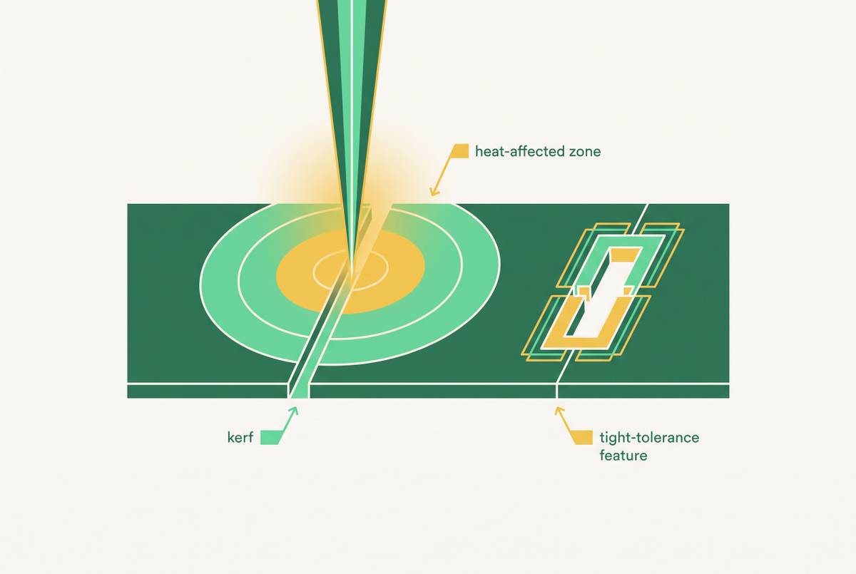
Laser cutting is the sharpest tool in the whole chain. Fiber laser systems hold roughly ±0.05 mm positional accuracy, which lines up with ISO 2768's Fine (f) class, the tightest band the standard offers; Manufyn reports this figure. Nothing downstream comes close.
Forming tells a different story, and fabrication data breaks it out by dimension type:
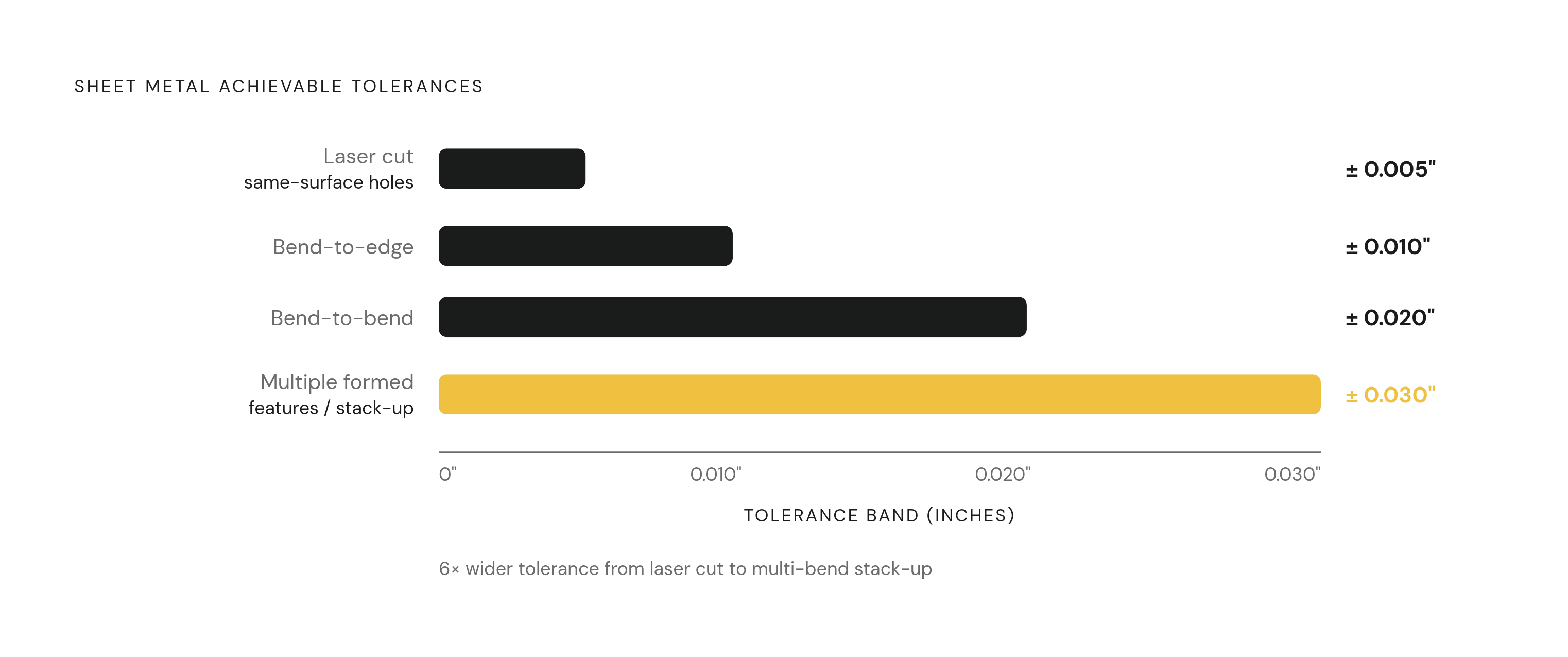
- Features on the same flat surface: ±0.005", governed by laser or punch accuracy alone
- Bend-to-edge dimensions: ±0.010", once material thickness, springback, and tooling variation enter the picture
- Bend-to-bend dimensions: ±0.020", where multiple forming operations start stacking
- Multiple formed features together: up to roughly ±0.030", since each added bend contributes its own slice of variation
Angle has its own failure mode. Standard air bending drifts, and once that drift passes ±1.0°, parts start jamming at welding stations. A closed-loop laser bending process holds within ±0.5°, but that's a different setup than a standard press brake run, and it needs to be specified, not assumed.
Springback complicates things further, and it's material-specific. High-strength alloys can spring back harder after bending, with bend angles shifting by up to 1.5° after cold press-brake bending. That has to get compensated at the design stage. Catching it at inspection is too late; by then the part is already out of spec and there's no fixing it without reworking the bend.
Close-tolerance sheet metal exists too, for parts that need to nest, seal, or mate against precision-machined components. Critical features can be held to ±0.002" to ±0.005", but that's a different cost tier entirely, with different tooling and inspection behind it.
The pattern across all of it: feature type determines process, process determines what's achievable. Knowing which regime a given feature lives in is most of the job.
How variation accumulates across bends, and why datum choice controls the damage
Bends don't cancel each other out. Each one adds its own slice of variation, and in a multi-bend part, those slices stack in the worst-case direction, not toward some friendly average.
A worked example on a two-part L-bracket assembly shows the arithmetic: each part carries ±0.3 mm of formed tolerance on its own. Putting two of them together at a joint doubles the worst-case mating error to ±0.6 mm. If the assembly needs joint alignment within ±0.3 mm, there are really only two paths forward: tighten each part's tolerance down to ±0.15 mm, which gets expensive fast, or design in a feature that locates the parts mechanically instead of relying on tolerance alone.
Datum choice decides whether formed variation even enters the measurement chain in the first place. A datum built off a mounting surface and a set of locating holes gives the fabricator a fixed, stable reference to measure from. A datum built off a formed edge drags bend variation into every single measurement taken from it, which makes it a poor choice for any cross-bend dimension.
Position tolerances on hole patterns are considered some of the highest-value GD&T on a sheet metal drawing. Position controls whether a pattern actually fits, and it usually gives the fabricator more manufacturing freedom than a coordinate-style tolerance would.
Self-locating geometry is the structural answer to all of this. Tab-and-slot pairs, or a pilot hole paired with a pin, register parts against each other mechanically, regardless of how much dimensional variation crept in upstream. That takes the pressure off the tolerance callout entirely.
The practical version of all this follows a two-tier approach: leave genuinely noncritical dimensions at the validated default, whether that's ISO 2768-m or the equivalent ASME table, and override only where fit, bend behavior, hardware installation, or an inspection outcome actually depends on it. One chain, from function to process to inspection, with nothing left loose in the middle.
Feature-by-feature tolerance decisions: where to hold tight, where to let go
Laser-cut holes and slots on the same flat plane. The process holds ±0.05 mm at the cutting stage, and ±0.005" on same-surface hole patterns is standard practice. These are the features that can carry position GD&T for connectors, mounting hardware, or bolt patterns without much of a cost hit, because the process was already capable of it before anyone wrote the tolerance down. Holes need to sit at least 3 to 4 times the material thickness away from a bend line. A hole placed inside that zone distorts during forming no matter how tight the cutting tolerance was.
Bend angles: standard air bending isn't a precision process, and deviations past ±1.0° start jamming assemblies. If a design's fit genuinely depends on angle, call out ±0.5° explicitly and confirm the fabricator has closed-loop angle correction available, because achieving that angle reliably requires confirmed closed-loop angle correction capability. Springback compensation belongs to the fabricator's process, not the drawing note, but flagging which angles matter is the engineer's job.
Cross-bend dimensions are the expensive ones to tighten, since every bend in the chain adds its own error. Standard practice runs ±0.020" bend-to-bend, stretching to ±0.030" once multiple formed features are involved. Where assembly fit needs something tighter than that, look at self-locating geometry or a secondary machining step before writing down a number the press brake can't hit consistently.
Flange length should be kept above 4 times material thickness, or the press brake loses its grip and the angle drifts. A flange that breaks this rule generates angle variation no drawing callout can fix. That's a geometry problem, and it needs a geometry solution.
Bend radius: minimum inside radius should be 1 times material thickness for most common alloys (5052-H32 aluminum, 304 stainless, 1018 cold-rolled steel). 6061-T6 needs more room, at least 3 times thickness, because it's less ductile; EPOC CRAFTER reports this. Going under that radius causes the material to crack. Going over that radius while still demanding a tight cross-bend tolerance asks the drawing for two things that can't coexist.
The dimensions that actually control fit and function should be identified, everything else should be left at ISO 2768-m, and self-locating geometry should handle cross-bend alignment instead of stacking tighter tolerances on top of a process that wasn't built for it; this is the cause behind the tolerance problems described above, producing the cost and fit issues seen when tolerances are stacked instead.
Surface finish as a hidden tolerance variable
Finish adds material. That sounds obvious once it's said out loud, but a surprising number of drawings tolerance the bare part and never account for what the coating does to it afterward. A part that fits perfectly off the press brake can fail to assemble once it comes back from finishing.
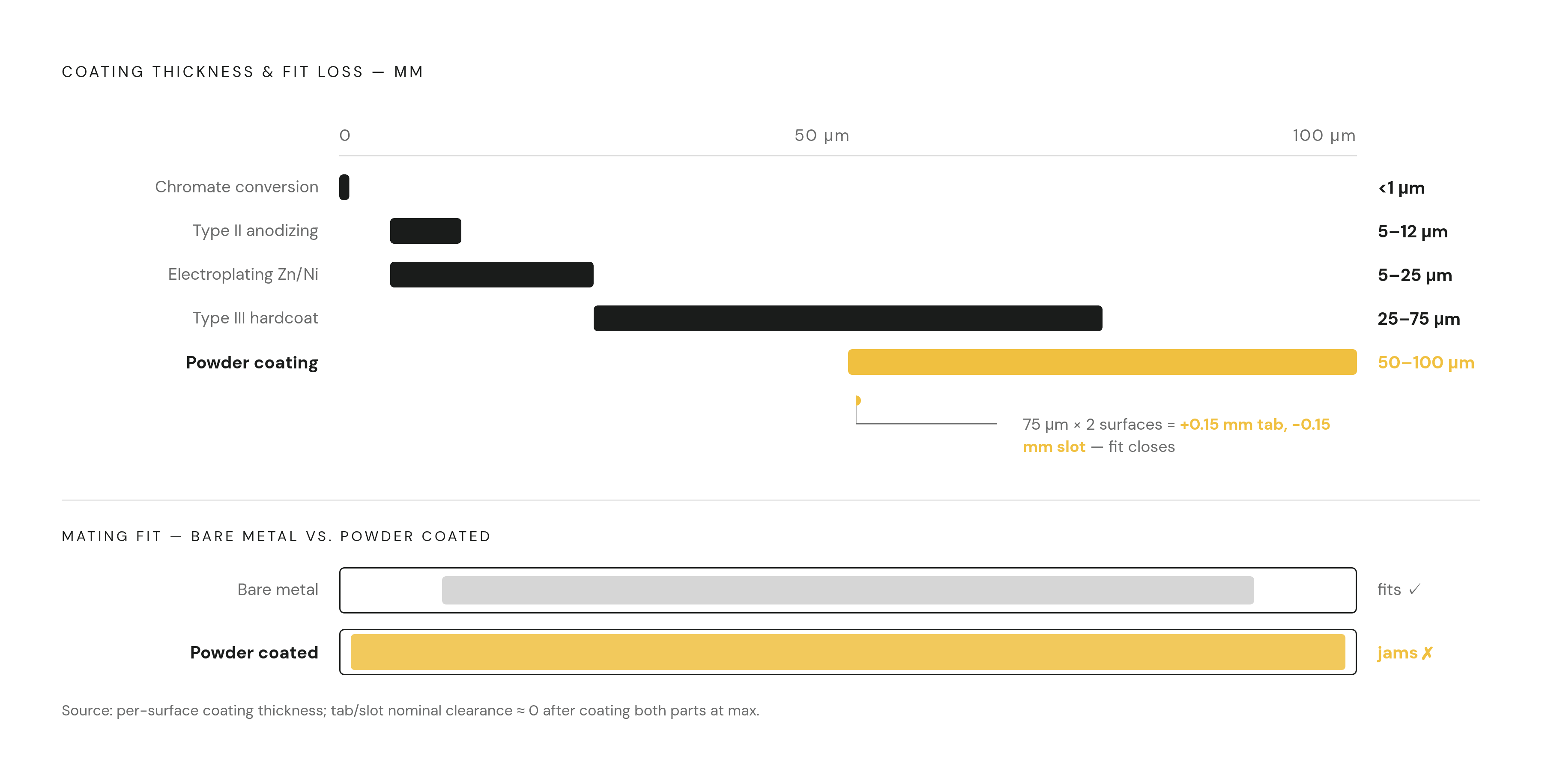
Coating thickness varies a good deal by process, and EPOC CRAFTER's figures lay out the range:
- Powder coating: 50 to 100 μm per surface
- Type II anodizing: 5 to 12 μm
- Type III hardcoat anodizing: 25 to 75 μm
- Electroplating, zinc or nickel: 5 to 25 μm
- Chromate conversion (Alodine or chem film): negligible thickness addition
The damage is worst on slot-and-tab fits, where two surfaces are both gaining thickness at once. As epocrafter.com's worked example shows, powder coating both parts at 75 μm per surface adds 0.15 mm to tab width and removes 0.15 mm from the slot opening. A fit that worked fine on bare metal closes up entirely once the finish goes on.
The fix has to happen at the drawing stage, not after the fact. Pre-coat dimensions on any mating feature need to build in the coating budget from the start. Anywhere the finish isn't chromate conversion, nominal clearance on slot-and-tab geometry should be sized for the coated part, not the as-cut one.
Tolerance strategy for parts that must mate with machined components
Once a sheet metal part has to seal against a gasket, register on a precision bore, or mate up with a CNC-machined piece, standard fabrication tolerance isn't enough anymore, and that calls for a deliberate decision rather than a default.
Jushunmetal's guide on close-tolerance sheet metal assembly puts the achievable range for critical features on mixed-process assemblies at ±0.002" to ±0.005". Getting there needs dedicated tooling, fixtures, and more inspection than a standard run, so it costs more, in its own tier above ordinary fabrication.
Secondary machining is often the more sensible route. Rather than tolerancing an entire formed part down to close-tolerance levels, machining just the one surface that needs the precision interface, after forming, usually costs less and gets a cleaner result.
The decision that matters here: figure out which features actually touch the machined component, apply the tight callout only to those, and leave everything else at the validated default tolerance. There's a sourcing angle too. Parts that combine forming with secondary machining need either a supplier who can run both operations or an assembler who can manage the handoff tolerance between two separate vendors. Keeping it under one supplier takes the inter-vendor stack-up out of the equation entirely.
Running a tolerance audit on your drawing before it reaches the fabricator
Think of this as a gate-by-gate check on the flat pattern, run before the drawing ever leaves the building.
Gate 1, title block: is ISO 2768-m, or the ASME equivalent table, declared on the drawing? Every dimension without an explicit override should fall under a validated default. Nothing should be left open to the fabricator's guess.
Gate 2, feature placement: do all the holes, slots, and cutouts clear 3 to 4 times material thickness from the nearest bend line? Anything inside that zone distorts during forming, and no tolerance callout changes that outcome.
Gate 3, bend angles: is any angle actually functionally critical? If a deviation past ±1.0° would cause interference at assembly, write ±0.5° on the drawing and confirm the fabricator can hold it. Standard air bending won't get there by default.
Gate 4, cross-bend dimensions: trace every dimension that spans a bend. Confirm the ±0.020" bend-to-bend standard actually works for assembly fit. If it doesn't, look at self-locating geometry before reaching for a tighter callout the process can't reliably hit.
Gate 5, datum selection: are the datums anchored on stable machined or laser-cut references, or are they riding on formed edges? Move them off formed features wherever measurement stability matters.
Gate 6, coating offset: is the part getting a finish thicker than chromate conversion? If so, find every mating slot-and-tab feature and size the pre-coat clearance for the finished condition, not the bare one.
A DFM review closes the loop. LS Manufacturing's log across more than 1,200 parts run in 2025 and 2026 shows two-hour DFM reviews cutting defect rates down to 2.1%, catching the placement and geometry problems a pure tolerance check would miss. Running the gates and getting the review makes the drawing that reaches the fabricator say what the part needs, no more and no less.
Sources
- Sheet Metal Bending Errors: Holding ±0.5° Angle Tolerances
- Sheet Metal Design Guidelines: DFM Rules, Tolerances & Best Practices (2026) | EPOC CRAFTER
- Perfectly Formed Sheet Metal Parts (Updated for 2026) | ASM
- DFM: 15 Best Practices | MakerStage
- Sheet Metal Fabrication Tolerances: ISO 2768 Explained
- Close Tolerance Sheet Metal Assembly: Design & QC