Weld Distortion Control in Sheet Metal Fabricated Assemblies
Design and process choices set distortion limits before welding starts.
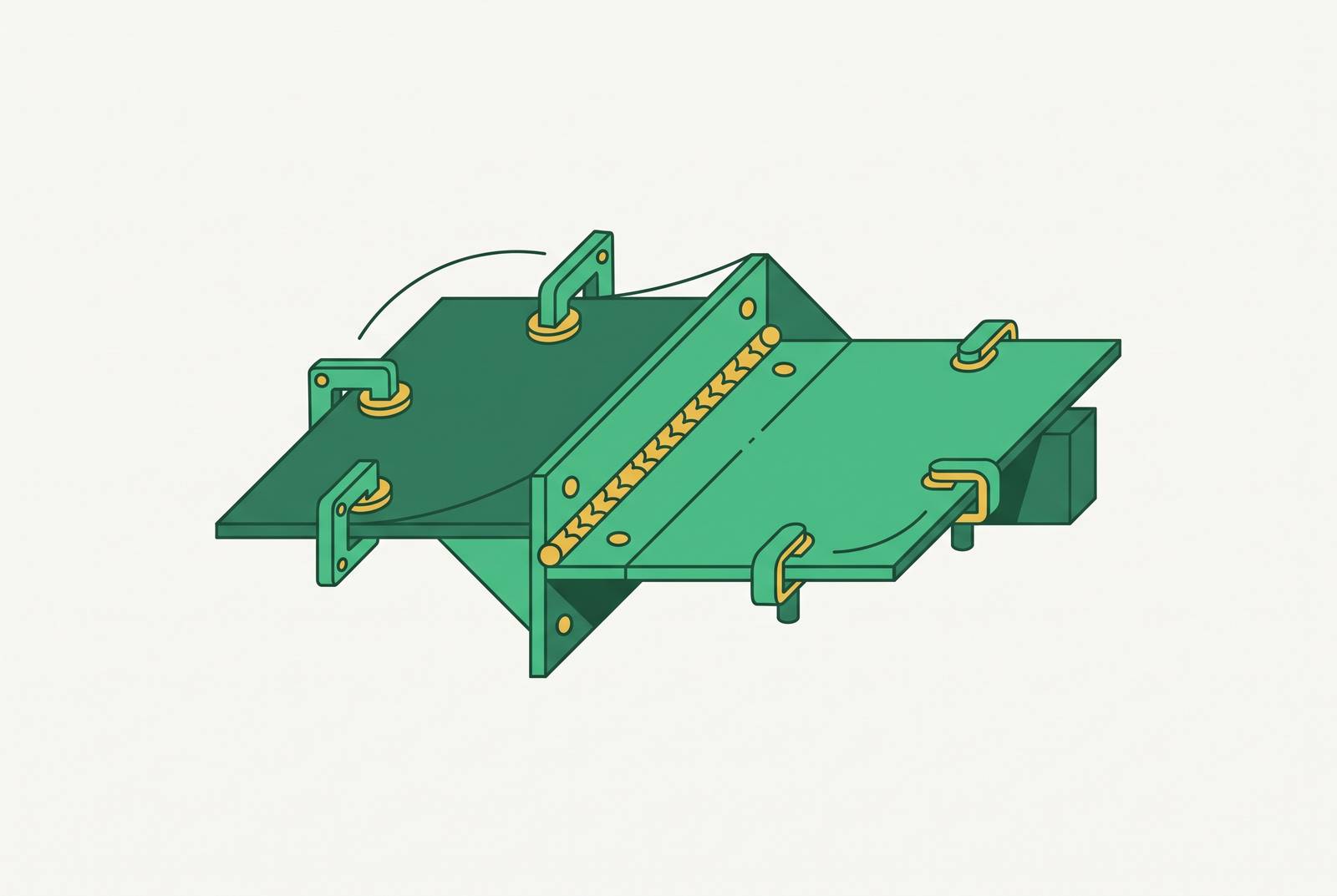
Weld distortion in sheet metal is physics doing what physics does: metal expands when heated, shrinks unevenly as it cools, and locks stress into whatever's left behind. Treating it as a skill problem, something you fix by training welders harder, misses where the real decisions get made. The design, the fixture, and the weld sequence decide the outcome before anyone strikes an arc.
Localized heating pushes weld-zone temperatures past 1,500°C, and the metal around that heat expands right along with it. Cooling then happens unevenly: fast at the surface, slower down at depth, faster near the bead than out at the part's edges. That mismatch traps tensile stress in the weld zone while compressive stress builds up in the surrounding material. Once that compression exceeds what the sheet can resist without buckling, the part moves. That's structural mechanics doing its job.
The stakes run higher than a cosmetic dent. Residual stresses in welded assemblies can reach magnitudes on par with, or beyond, the base material's yield strength. Distortion is a structural condition baked into the part. It's a structural condition baked into the part.
Thin-gauge stock, roughly 1mm to 3mm, takes the worst of it, since that's where the ratio of weld-zone stress to the section's ability to resist it peaks. It's consistently the top rejection cause for parts in that range, and the warp appears the second the clamps come off, after post-weld machining, or months later out in the field. Same stored energy, just a different exit point. Managing that energy budget upstream comes down to five decisions: which distortion mode you're fighting, what process and heat input you pick, how the joint gets sized, how the fixture restrains the part, and how the welds get sequenced.
Five distortion modes and their countermeasures
Distortion analysis commonly splits into two families: out-of-plane deflection and in-plane shrinkage. That split produces five specific modes, and each one needs its own fix, not a general appeal to "better technique."
Transverse shrinkage pulls material inward across the weld's width, narrowing the joint. Longitudinal shrinkage shortens the whole assembly along the seam, a real headache on long structural members. Angular distortion comes from uneven shrinkage through the material's thickness, tilting the angle between two joined faces; it's the usual suspect at fillet welds and single-bevel joints. Bowing happens when the weld sits off-center, curving the whole component, and it gets worse fast on asymmetric joints. Buckling is the one most specific to sheet metal: thin material loses stability under compression and ripples into waves or local bulges.
Section thickness, joint symmetry, and where the bead sits determine which mode occurs, not how clean the weld looks. On multi-pass welds, each pass stacks a bit more of the same distortion mode onto the last, so cumulative error across all passes can substantially exceed what any single pass would have caused alone.
A few patterns to watch for:
- Thin stock welded with long continuous beads produces bowing and buckling.
- Asymmetric joints produce angular distortion.
- Long seams welded without sequencing discipline build longitudinal shrinkage into a full-length bow.
Residual stress doesn't spread evenly, either. It concentrates at weld toes and at the start and stop points of each bead, and under cyclic loading those exact spots turn into fatigue cracks. Distortion and fatigue risk are two readings of the same thermal event, not two separate problems. Small errors from different welds stack across an assembly too, so one bracket twists a degree, a panel narrows a fraction of a millimeter, and a flange tips slightly. By final assembly that appears as faces that won't sit flush and fasteners that won't thread in.
Once the dominant mode is identified, the next decision carries the most weight in the whole process: heat input and process selection, made before fabrication starts.
Process selection and heat input set the distortion ceiling before fabrication begins
Heat input governs everything downstream of it. The formula: Heat Input (kJ/mm) equals voltage times current times 60, divided by travel speed times 1,000. Cutting any term in the numerator, or speeding up travel, drops the thermal volume the material has to soak up.
On thin-gauge sheet, roughly 8 gauge (0.164 inches) down to 30 gauge (0.012 inches), process choice sets a ceiling on how much distortion is even possible before the first pass goes down.
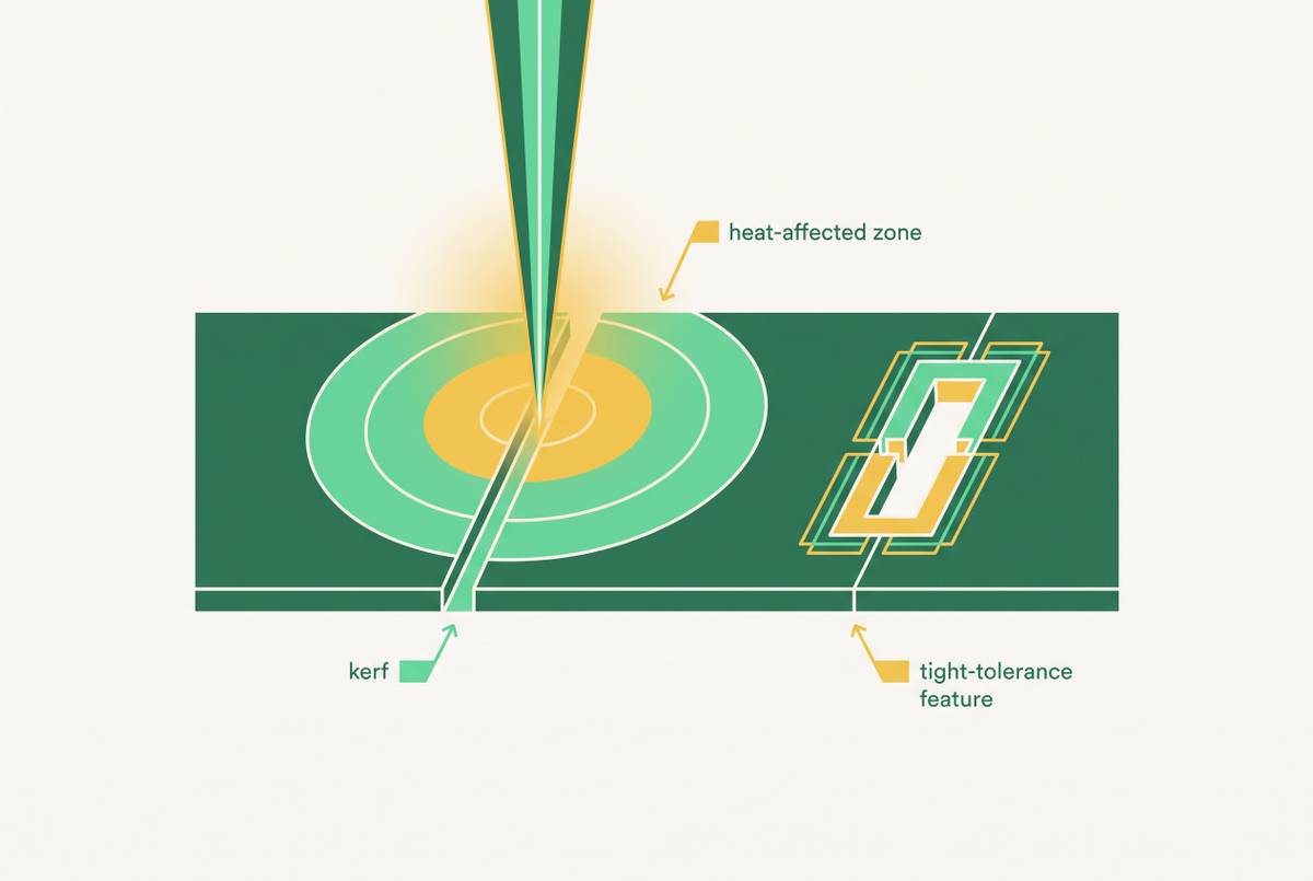
Laser welding puts energy into a tight, focused spot with a narrow heat-affected zone, and that alone gets close to zero distortion on thin stock. On 18-gauge carbon steel, Miller Welds reports that laser welding puts roughly half the total heat into the workpiece that TIG or MIG would.
TIG gives an operator precise control over penetration and bead size and leaves a clean seam, which makes it the right call for thin gauges and anything visible in the finished product. It runs slower than MIG, though, and takes more labor per foot of weld.
MIG runs faster and pushes more parts through the shop per hour. It also dumps more heat into the joint per unit length, which raises warping risk on thin sheet. Pulse MIG settings bring the average heat input down and keep distortion in check on thinner material, so if the shop is committed to MIG on thin gauge, pulse is not optional.
Resistance or spot welding fits lap joints in high-volume runs well, since heat stays tightly localized to the nugget with almost no spread into the surrounding HAZ. It just doesn't work for jobs that need a continuous sealed seam.
Laser equipment costs real money: top-tier industrial units typically run past $100,000, and that matters even when the part ships out to a fabrication partner instead of getting built in-house. Fit-up tolerance tightens up too. MIG bridges a gap of several millimeters without complaint, while standard laser welding wants a joint that's nearly gap-free. Wobble beam mode on newer systems helps, tolerating roughly 0.5 to 1.0mm. Even with those costs, switching repetitive seams on thin sheet (0.8 to 3mm, stainless or carbon steel) to handheld or robotic laser welding typically cuts cycle time per part by 30 to 50%, and it often eliminates the post-weld grinding step. On any high-volume thin-gauge job, that math closes fast.
Automated welding beats manual welding on consistency, too. It holds a narrower, steadier arc, and travel speed doesn't drift the way a hand does over a long seam. CO2 gas-shielded welding, run with thin wire and high current density, concentrates heat and cuts distortion compared to manual MIG on the same joint.
Whatever process gets picked, three settings still need tuning: voltage, current, and travel speed. All three interact, and tuning any one of them shifts the thermal load the part absorbs. Low voltage, high travel speed, and high current density together give the smallest distortion for a given process, and even holding current steady, pushing travel speed up lowers the line energy going into the part.
Specifying process on the drawing, or at minimum in the fabrication brief, is a distortion control decision in its own right. Leaving that choice to the fabricator leaves the single highest-leverage input in the whole system unmanaged, and that's a mistake shops make more often than they'd admit.
Joint design and weld sizing decisions that reduce distortion before a fixture is built
More weld metal means more shrinkage force pulling on the joint once it cools. Sizing a weld for what the joint actually needs to carry, no more, is a distortion control measure in its own right, and it's the cheapest one on this list.
The most common mistake appears right on the drawing: a full continuous weld called out on a non-structural cover or a cosmetic panel, where an intermittent weld, or even a mechanical fastener, would meet the load requirement with a fraction of the heat going into the part. It costs nothing to fix and gets overlooked constantly.
Joint geometry carries its own baggage. A single-V butt joint puts heat and shrinkage unevenly across the material's thickness, which makes angular distortion nearly guaranteed. A double-V butt joint balances the groove on both sides so shrinkage spreads symmetrically, and the angular distortion from one side largely cancels the other. That's the same principle behind balanced weld sequencing: cancellation beats resistance every time.
A smaller included angle means less weld metal fills the joint, and small changes in groove angle produce an outsized drop in total shrinkage force. Where the weld sits relative to the section's neutral axis matters too. Off-center placement generates a bending moment as the weld contracts, so centering or balancing weld placement cuts down on bowing directly.
Sometimes the better fix skips welding. Rivets, clinching, and self-piercing fasteners put no heat into the part, which makes them a strong option on thin gauges where distortion from any welding process becomes the real problem. The trade-off is added hardware weight and, on some joints, lower stiffness. Structural adhesives spread load across a large bonded area with next to zero thermal distortion, and they work especially well on cosmetic panels or joints between dissimilar materials, where surface finish is the priority over raw strength.
Ask whether the joint actually needs the continuous sealed perimeter or the load capacity that only welding delivers. If it doesn't, a non-weld method wins on distortion grounds, full stop, no further debate needed.
Sheet metal in a welding context runs 30 gauge (0.012 inches) up to 8 gauge (0.164 inches). Below about 3mm, roughly 11-gauge, buckling and angular distortion become especially prominent concerns, and that's exactly where joint design decisions carry the most weight.
Fixturing strategy: how mechanical restraint shapes the distortion outcome
A properly built fixture stops the part from moving as a whole. That forces shrinkage to get absorbed as plastic deformation inside the weld zone instead of as visible movement across the assembly. The part yields internally instead of shifting externally, and that difference is the entire point of building a fixture instead of just clamping something down and hoping.
In any production run building multiple identical assemblies, rigid fixturing is the most repeatable distortion control method available. Nothing else comes close on repeat runs. Repeatability separates real fixture design from clamping something down by feel each time and hoping it comes out the same as last time.
On material under 1.5mm (16-gauge), a heavy-duty clamp every 3 to 4 inches (75 to 100mm) along the joint is a reasonable starting point. Space clamps further apart than that, and the unsupported span between them bows.
Timing matters as much as spacing. Parts need to stay clamped not just during welding but until the steel cools fully to room temperature. Pulling the clamps early, while the part's still warm, gives residual stress a window to drive distortion before the material recovers its yield strength.
Heat-sink fixturing adds another layer. Copper or aluminum backing bars clamped behind the joint act like a sponge for thermal energy, pulling heat out before it soaks into the surrounding sheet. That gives strong welds with minimal HAZ spread and next to no distortion. Copper gets the nod most often for its conductivity. Water-cooled jigs push this further: copper tubing brazed to the holding clamps circulates water during welding, combining mechanical restraint with active heat extraction, which matters most on thin stainless where HAZ sensitivity runs high.
A few rules apply across the board. Fixture stiffness has to exceed the shrinkage force the weld will generate, or the fixture flexes and gives a false sense of control. The fixture also has to allow thermal expansion while the part heats, while still stopping net displacement once it cools. Clamp down too rigidly and trap that expansion, and cracking becomes the real risk instead of controlled distortion. On complex assemblies, load order into the fixture changes how much restraint is available at each weld, so fixture design and weld sequence need planning together as one problem, since each one shapes what the other can do.
Tack welds deserve a mention of their own. They act as a distributed, preliminary fixture built right into the joint, and placed well and sized right, they resist early movement before the final passes go in. Undersized tacks are a quiet, frequent source of distortion: they simply give way under the shrinkage force of the first full bead.
Fixturing restrains the part. Sequencing decides how thermal energy distributes inside that restraint. The two work as a pair, and neither one fixes distortion working alone.
Weld sequencing techniques that distribute heat and cancel shrinkage forces
Shrinkage doesn't disappear with good sequencing. What changes is its direction and timing, so forces from different welds cancel each other out instead of piling up in one place.
Stitch welding, sometimes called skip welding, breaks a long seam into short segments placed at intervals instead of one continuous bead. That keeps heat from building progressively down the joint's length. A second pass fills the gaps once the first set of stitches has cooled, spreading thermal load across both time and space. It's the main tool for heading off buckling in thin panels with long seams.
Backstep welding also breaks a long seam into short segments, but welds each one in the direction opposite the overall progression of the joint. That spreads heat more evenly and stops the progressive buildup that drives longitudinal bow. It's also one of the few genuinely free distortion controls available: no extra equipment, just a different order of operations, and there's no excuse for skipping it on long seams.
Balanced welding alternates passes from one side of the assembly to the other so each pass's shrinkage force offsets the one before it. Welding an entire joint from a single side produces noticeably more distortion than alternating sides, and this only works when joint geometry allows access from both faces.
For paired parts, the back-to-back technique clamps two identical assemblies together, welds both completely, and lets them cool before releasing the clamps. Shrinkage forces from each half pull against the other and largely cancel out, so net distortion on matched pairs approaches zero. It's especially strong on flat panel assemblies built in pairs.
Pre-deformation, also called pre-cambering or presetting, takes a different approach entirely: it accepts that some distortion is coming and works around it instead of fighting it. The sheet gets clamped with a reverse curve, typically 2 to 3 degrees opposite the direction the warp is expected to go. As the weld cools and contracts, the shrinkage force pulls the metal back toward flat, or toward whatever the intended final geometry is. Calibrating that preset angle takes real judgment, since the right value depends on material, thickness, joint type, and heat input, and no formula replaces a first-article check before full production runs.
Interpass cooling discipline rounds out the toolkit. Letting temperature drop between passes keeps heat from stacking pass over pass, the exact principle stitch welding and backstep welding run on, just applied inside a single joint instead of across a whole seam.
Sources
- Welding Distortion: Causes, Prevention, and Repair
- Welding Distortion Control: Techniques for Thin Plates | MachineMFG
- Weld Distortion
- Reducing Welding Deformation on Large Sheet Metal Assemblies: Fixturing, Sequencing & Stress Relief - Baosheng
- janeemachining.com
- Welding Distortion: Tips to Control It Like A Pro | MachineMFG
- 1cutfab.com