Process Sequencing for Machined and Anodized Aluminum Parts
Oxide growth during anodizing shrinks bores and expands shafts unpredictably.
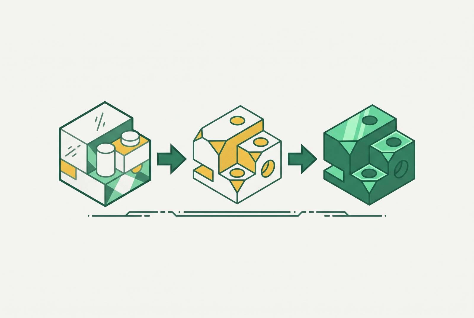
Process sequencing for machined and anodized aluminum parts requires designing for the finished condition after both CNC machining and anodizing. A clean result depends on decisions made before and between operations, including alloy selection, surface preparation, oxide-growth compensation, and rack placement. A platform for sourcing a multi-process mechanical assembly can bring those decisions into one conversation about the quote, but the drawing must still spell out the result.
Why the sequence of machining and anodizing determines the outcome — not either process alone
A bore can pass inspection after machining and bind after anodizing. The cut may have met its tolerance, yet that tolerance meant little if nobody accounted for the oxide that would grow into the opening. A cosmetic face can fail for the same underlying reason when anodizing preserves scratches that were left for the finishing shop to fix.
The two processes are linked because anodizing converts the surface into aluminum oxide, so the CNC machine creates the geometry from which the finished layer grows. Every tolerance, edge, and surface condition stays with the part. The sequence controls whether those inherited conditions produce an acceptable part.
How the oxide layer physically grows and what that means for machined dimensions
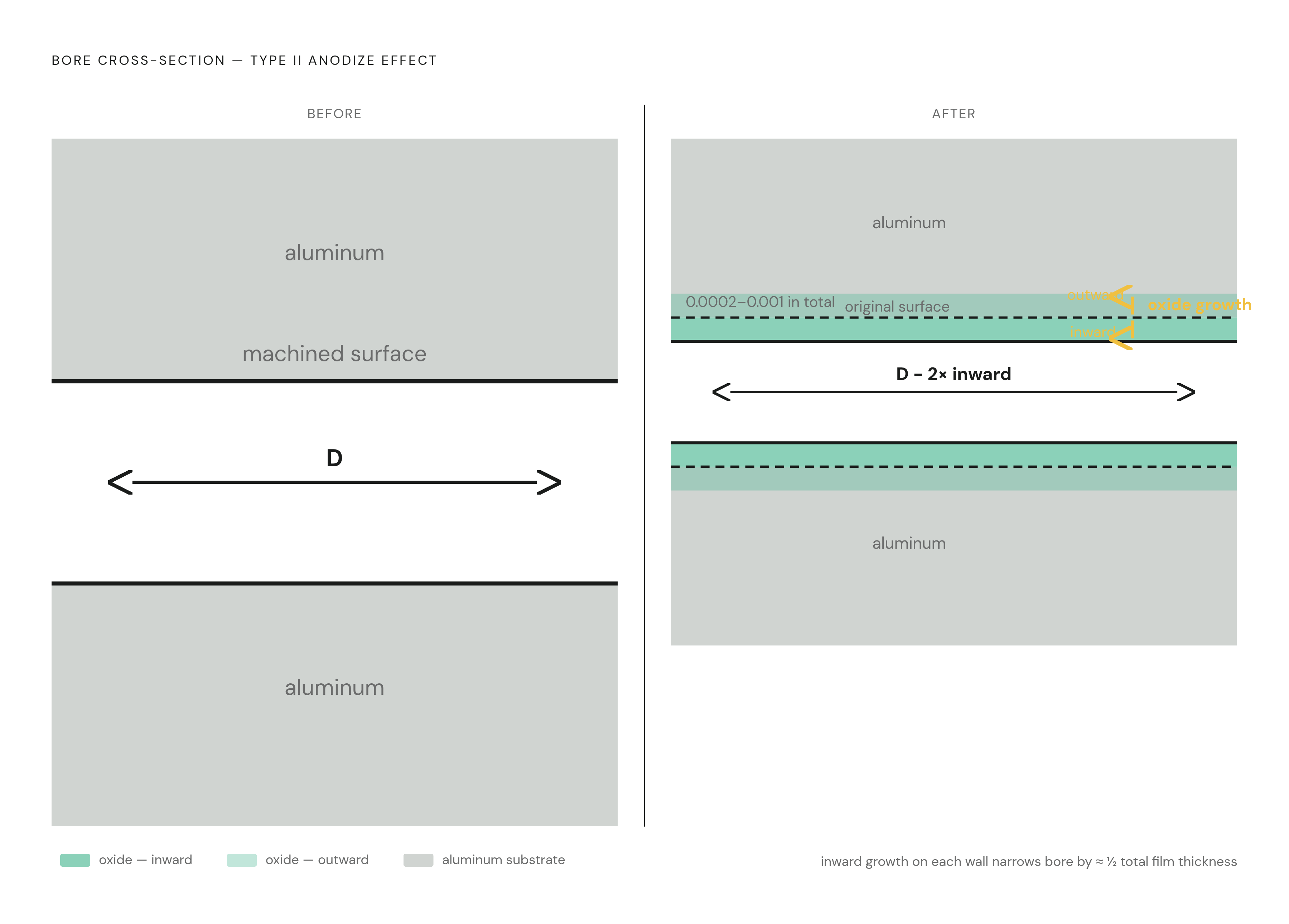
Picture a cross-section with a line where the original machined surface was. After anodizing, some of the oxide lies below that line, where aluminum has been converted, and some lies above it. The layer therefore grows both into and out of the original surface. Its full thickness is not the same as its outward growth. On an external feature, outward growth adds size, while inside a bore it narrows the opening.
Type II sulfuric acid anodizing produces film thicknesses in the range of 0.0002 to 0.001 inches. That range is not a safe default for a drawing or a machining offset. The thickness and expected outward growth must be confirmed with the anodizing shop for the specific run. Even within this range, uncompensated growth can bind a thread or push a fitted feature outside its tolerance.
Type III hardcoat forms a thicker, denser layer for parts where wear is critical, such as gears and industrial machinery. Because it grows more, it needs more pre-anodize compensation. Type I is an option when tight dimensional tolerances drive the choice. The process type therefore belongs in the dimensional plan before geometry is fixed.
Choosing the right aluminum alloy before the first cut, because alloy choice constrains everything downstream
That dimensional plan starts with an alloy that can deliver the required finish. The brief’s strongest choices for cosmetic and performance anodizing results are 6061 and 5052. For engineers new to anodized-part design, 6061-T6 is the recommended starting point because it machines quickly, holds tolerances well, and produces a consistent surface finish with minimal tool wear. Good sequencing cannot make every alloy respond equally well.
High-copper alloys such as 2024 can produce dull or uneven anodized finishes. They should be avoided where appearance or coating uniformity matters. A higher-strength alloy may still be justified by the design, but its less uniform finish is a trade-off to accept before production. Temper also affects machinability and how evenly the surface responds to the anodizing bath.
These choices belong in the quote review because changing them later means revisiting a committed design. OneWeekParts flags alloy-to-anodize mismatches and tolerance strategy during instant quoting, before tooling starts. That is one way to bring the material and finishing decisions together early. Select aluminum that cuts well and can meet the finished requirement.
What the machined surface must look like before the part enters the anodizing tank
Once the material is selected, the machinist must deliver a surface that is ready to be preserved. Etching and pre-treatment can make fine tool marks less pronounced, but they cannot fix a surface that is rough overall or remove deep scratches. Machining marks, bead blasting lines, and polishing patterns can remain visible after anodizing. Anodizing reveals the surface it receives.
Geometry matters as much as texture. Anodic coatings are thinner at sharp internal corners and edges, so those areas have too little protection. Blind holes create a different problem because electrolyte trapped in a deep cavity can cause internal corrosion or blooming after sealing. Through-holes should be used where function allows them. Where a blind hole is unavoidable, its design must allow drainage during processing, rather than leaving trapped liquid as a problem for the finished part.
Pre-anodize cleaning as a process step that controls coating quality independently of machining quality
A well-machined surface can still anodize badly if contamination reaches the tank with it. Coolant residue, polishing compound, fingerprints, oil, and trapped debris interfere with oxide growth. The resulting visible defects can survive sealing. Surface accuracy and surface cleanliness are separate requirements, so passing machining inspection does not make a part ready for anodizing.
The anodizing shop’s cleaning sequence includes degreasing, etching, and rinsing. Those steps are meant to remove contamination, but standard pre-treatment may leave some heavy coolant residue or oxidation inside small features. The engineer and machinist therefore share responsibility for what arrives at the shop. For cosmetic parts, that means specifying clean-room packaging after machining and avoiding bare-hand contact with critical surfaces. Coolant must also be fully evacuated from blind holes and recesses before shipment.
A single facility handling machining and anodizing under one quality system substantially reduces this handoff risk. Parts can go straight from machining to pre-treatment without being shipped elsewhere or repackaged.
Tolerance compensation for oxide growth — how to set pre-anodize dimensions correctly
The finished dimension is the engineering requirement, and the machining dimension must be derived from it. Every fitted bore, shaft, and thread needs room for the oxide growth that is expected. Compensation is not optional just because the coating is thin. If its effect matters to the fit, it belongs in the machining target.
If the drawing calls for a final bore diameter of X after Type II anodizing, the pre-anodize bore must be larger than X by the amount of outward growth expected on both opposing walls. The outward-growing portion of the oxide film fills this allowance as it grows into the opening, bringing the bore toward the required finished diameter. Because the notes give no fixed grow-in/grow-out ratio, the numerical offset must be based on the agreed process. The shop must also check that the variation it expects is within the finished tolerance.
For an external shaft, the direction reverses. The pre-anodize diameter must be smaller than the final diameter by the expected outward growth on both sides. Without that correction, a shaft intended to have clearance can become an interference fit. For M4 and below, standard tap sizing without compensation routinely leads to binding or cross-threading after Type II anodizing, so an oversized tap must be chosen before finishing to allow for the oxide growth that is expected.
The drawing must make ownership of these dimensions explicit. An ambiguous bore callout can leave machining and anodizing working to different interpretations, especially when the tolerance band is smaller than the coating thickness. Every fitted bore should state whether its dimension is before or after anodizing and give the corresponding offset. During quoting through platforms such as OneWeekParts, design-for-manufacturing feedback allows engineers to validate that strategy against the selected anodizing type before the first cut. Cutting a bore after anodizing is not an equivalent correction because it removes the coating the dimensional plan was meant to preserve.
Racking contact points and where jig marks end up on the finished part
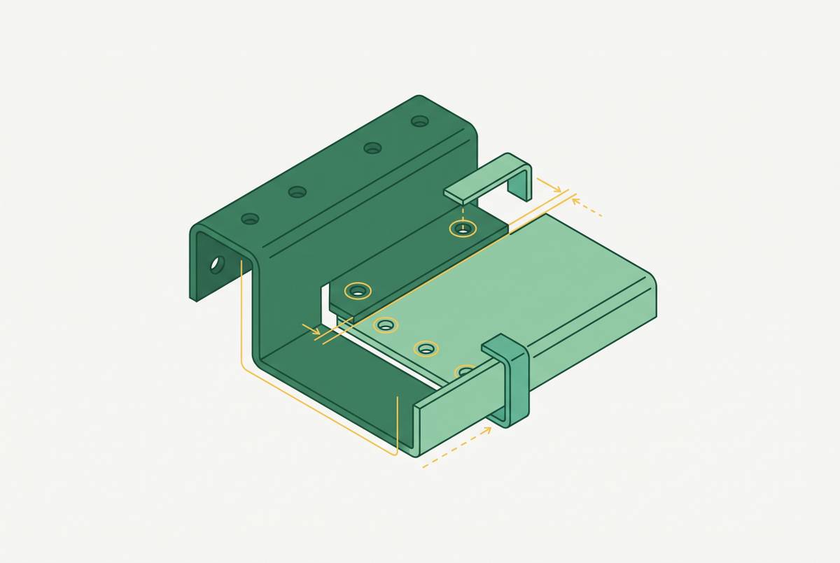
Dimensional planning does not remove the anodizer’s need to hold the part in an electrical circuit. Every part must contact the rack, and that contact leaves a small uncoated area called a jig mark. The mark is unavoidable, but its location is controllable. The drawing should designate a non-critical face or boss, ideally one hidden in the assembly.
Without that callout, the anodizing shop chooses where to make contact and may not know how the part fits into the assembly. Its choice may land on a cosmetic face, sealing surface, or bore that needs full coverage. Confirm the designated area with the shop before production so its racking geometry can reach it. Where no surface is suitable, a small sacrificial tab or boss can serve as the contact point and be machined away afterward as a planned exception to the normal sequence.
When post-anodize machining is acceptable and when it destroys the coating's purpose
The idea that a part can always be cleaned up after anodizing is a poor basis for a process plan. Every cutting surface removes or breaches the oxide and exposes bare aluminum. At that location, machining takes away the corrosion resistance, surface hardness, and cosmetic finish that anodizing was meant to provide. It may restore a dimension while defeating the reason for the coating.
There are narrow uses for post-anodize machining, including removing a sacrificial rack tab, final-cutting a critical bore that cannot be compensated accurately enough beforehand, or facing a datum whose tolerance is tighter than the anodizing process variation allows. Each is a defined engineering choice. If the cut exposes a functional or corrosion-critical surface, that exposure must be addressed. Options include a compatible touch-up coating, an anodize-safe sealant, or an explicitly documented acceptance of the limitation.
Fatigue-critical parts add another concern because the anodized layer, particularly Type III hardcoat, is brittle. Under cyclic loading, micro-cracks can propagate into the substrate, while machining afterward removes even intact coating and its local surface-hardening benefit. Machining after anodizing needs a clear reason, since a vague promise to adjust the part at the end is not enough. The default is to complete machining first and compensate for oxide growth. The earlier sequencing decisions exist precisely so that unplanned machining after anodizing is not needed.
How to get a single quote with the drawing and anodizing requirements fully specified
The quote package is where the process plan becomes an instruction that suppliers can price and execute. A drawing without the anodizing type, coating thickness range, and dimensional reference state is incomplete. It leaves the supplier to assume requirements that may not match the design. A single quote does not remove that ambiguity unless the package defines the finished part.
The drawing must state Type I, II, or III and the applicable specification or standard. It must also give the minimum and maximum coating thickness, since tighter ranges cost more and need more control over the process. Each fitted feature needs an explicit “DIMENSION AFTER ANODIZING” or “DIMENSION BEFORE ANODIZING” note, with the pre-anodize offset stated numerically. The rack contact area must be identified by surface ID or note and agreed with the anodizing shop.
Call for natural/clear, black, or the required color standard where it applies. Because dye uptake varies with alloy and surface preparation, a color-match requirement may also need first-article approval. The drawing must show how much of each surface to mask, whether that calls for plugs in threaded holes, tape on mating faces, or full feature masking.
The complete package includes a STEP-format 3D CAD file, the 2D drawing, material grade and temper, required quantity, and target delivery date. For buyers seeking one quote for a multi-process mechanical assembly, the useful comparison is whether machining, finishing, and assembly requirements are reviewed together before production. One option is OneWeekParts, which handles CNC machining, finishing, and assembly through a single quote and purchase order, with anodizing feedback included in quoting. Consolidating the mechanical BOM this way reduces inter-vendor ambiguity over offsets and rack placement. The practical goal is one agreed definition of the finished part before any metal is cut.