Fabricated and Welded Frame Assembly Tolerances Across Multiple Parts
Tolerances for welded frames must account for cumulative error across cutting, bending, and welding.
A fabricated and welded frame assembly needs a tolerance plan for the whole chain. For buyers evaluating a multi-process mechanical assembly sourcing platform, the key requirement is a partner who reviews the complete assembly before quoting. Cutting, bending, fit-up, and welding all contribute variation, so a frame that closes at assembly starts with a design that accounts for their combined effects.
Why welded frame assemblies cannot be held to single-part tolerances
A frame can contain parts that each passed inspection and still fail to close at assembly. Its brackets may be acceptable on their own, yet their holes will not line up when brought together. The finished frame may also miss its required overall size or leave a mating part sitting at an angle.
The drawing error behind this failure is treating a weldment like a single cut part. A welded frame inherits variation from every operation used to make its members, then gains further movement as the welds cool. Paragon Metal Fabricators states that a laser-cut blank, bent four times and then welded into an assembly, can accumulate three to five times the error of a simple cut part. Applying the blank’s tolerance to the completed frame ignores that change in process.
How each fabrication operation contributes its own error floor
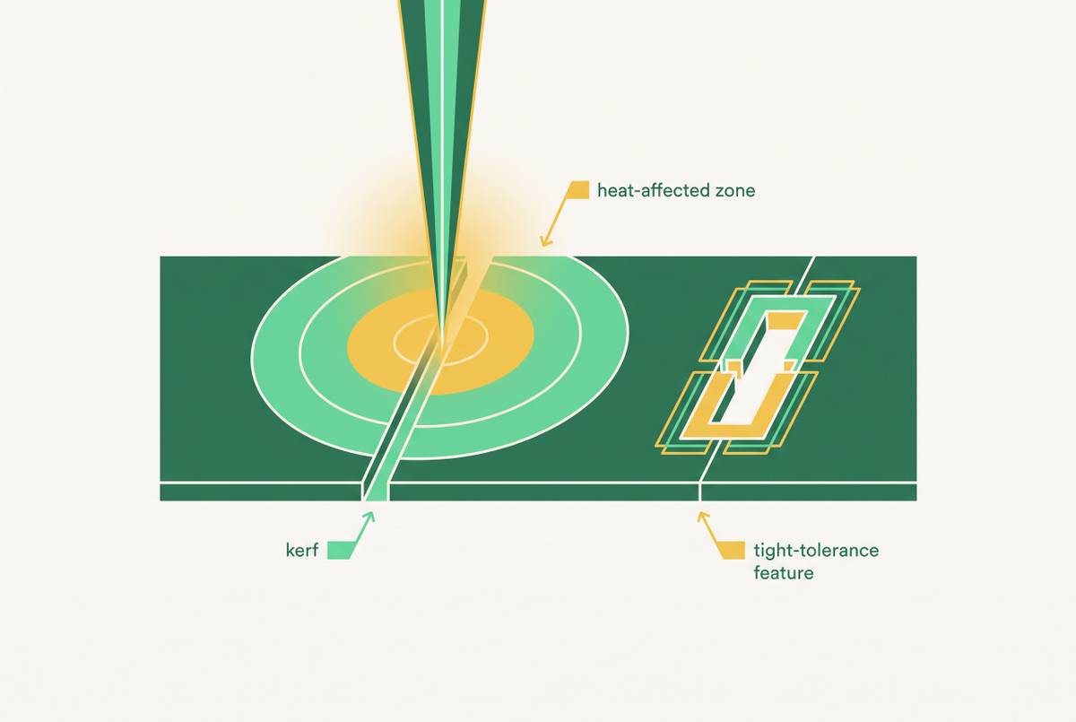
Cutting establishes the first set of dimensions, but its accuracy has a limited reach. Paragon puts laser-cut holes at ±0.005 in. on a flat blank. That figure applies only to features on the same flat surface before bending. The drawing cannot make that distinction disappear.
Bending adds variation in both the angle and the location of a bend. Standard shop practice puts angular tolerance at ±1° per bend and bend-line location at ±0.015–0.030 in., with springback depending on the material and setup. Each bend after that adds to the variation in the finished geometry. Features that cross a bend or span formed surfaces can open to ±0.015–0.030 in. before welding begins. Sheet thickness also varies, and thicker-than-nominal material can produce more springback and behave differently during fit-up.
Fit-up brings together parts that already vary in these ways. Their cut edges, formed angles, and thicknesses determine the gaps and relationships available for tacking. Welding then adds expansion as the parts heat up and contraction as they cool. Paragon gives ±1/16 in. as an overall-dimension tolerance for smaller structural weldments, widening for larger frames. That post-weld assembly tolerance requires accounting for upstream variation and applying the allowance only to the overall dimensions it covers.
Heat also means that welding errors can fall within an especially wide range. Thin material distorts more than heavy plate, while stainless steel distorts more than mild steel because of its lower thermal conductivity and higher thermal expansion. The choice of process and material thus sets how much of the tolerance budget is left before the assembly reaches inspection.
The tolerance chain — how individual part variations combine into an assembly problem
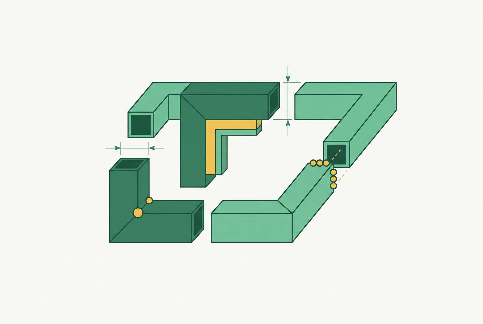
Consider three sheet-metal components that together make up a frame’s overall length. Each component can be within its own length tolerance while sitting toward the long end of its allowed range. When assembled, their combined length can exceed the frame’s overall limit. The design has allowed a combination that the assembly cannot accept.
The tolerance chain is the path between the two features that define a functional requirement. That requirement might be a gap, a hole alignment, an overall envelope, or the parallelism of mating faces. Every contributing dimension along the path belongs in the analysis, including the relationships created during forming and fit-up. A frame has several of these paths at once. Even when its overall length is right, its brackets may still be out of alignment.
Chain dimensioning makes the problem harder because each feature is located from the previous one. Errors then accumulate through the sequence. This can leave holes that fasteners struggle to fit through, weld gaps that are too large, or angular errors that leave downstream parts skewed. The effect depends on which dimensions connect the functional features.
The analysis method should match the consequence of failure. Worst-case analysis is appropriate when assembly failure is unacceptable, including safety-critical structures. Root sum square, or RSS, suits work where some statistical risk is acceptable and tighter tolerances on every part in the chain would cost too much. Statistical treatment is not a substitute for deciding how much assembly risk the design can tolerate.
Which standards actually govern welded assemblies — and why using the wrong one causes drawing errors
An engineer writing the assembly drawing needs to know how general weldment tolerances differ from welding process requirements. They answer different questions. The first defines acceptable finished geometry, while the second establishes the rules for making and inspecting the welds. A reference that covers one does not replace the other.
ISO 2768 is a common title-block choice for features produced by mechanical means, but it does not account for welding’s thermal distortion. Applying it as a blanket weldment tolerance can impose requirements suited to a flat blank. For small features, those requirements can be as tight as ±0.005 in., although they scale with size. The drawing may look sound but ask for geometry that the chosen fabrication route cannot reliably produce.
ISO 13920 (General Tolerances for Welded Constructions) addresses the weldment itself. It defines four classes for linear and angular dimensions, A through D, and four for geometric form, E through H. ISO 13920-BE is a practical starting specification for an assembly needing good functional accuracy, using linear Class B and form Class E. Critical features still need requirements tied to their function.
The applicable AWS code belongs on the drawing as well. AWS D1.1/D1.1M is the American Welding Society’s structural steel welding code, and which code to use depends on the material, what the joint does, and the thickness. Atlas Manufacturing explains that this choice establishes the applicable procedure qualification, welder qualification, and inspection rules. AWS D1.1 requires inspection throughout welding as well as at delivery.
The practical specification therefore needs ISO 13920 or an equivalent for the weldment and the applicable AWS code for welding. Without that distinction, a fabricator may reject the job, add unrequested post-weld machining, or deliver nonconforming parts.
How GD&T and datum strategy reduce stack-up without tightening every tolerance
Geometric dimensioning and tolerancing, or GD&T, turns functional requirements into controls on the drawing. Its value is selective precision. Instead of tightening every dimension, the engineer identifies the relationships required for the frame to fit and work. A consistent datum structure then gives those relationships a common reference.
A position callout on a bracket’s bolt pattern, for example, controls the holes relative to the assembly datums rather than relying only on separate linear dimensions. That targets alignment with the mating part. A flatness callout on a mating face addresses the surface that must seat properly, rather than imposing equally tight requirements on unrelated frame surfaces.
Common datum references across the assembly also prevent location errors from chaining through one feature after another. They remove avoidable dependence on intermediate dimensions, which makes both the requirement and its inspection clearer. The GD&T should follow ASME Y14.5 or ISO 1101, whichever fits the other standards used on the drawing.
Slots and clearance holes at non-critical connections can accommodate variation without compromising the required function. Keeping a hole pattern on the same flat surface before bending, where the design allows it, also keeps errors from building up across bends. These design choices cost less than making every operation in the chain hold a tighter tolerance.
Distortion control during welding as a tolerance management strategy
The drawing controls what must be achieved, but the welding plan influences how much variation the process creates. Distortion is a predictable result of heat and shrinkage. Joint design, weld size, and weld sequence therefore belong in tolerance planning. They are not details to leave until fit-up fails.
Oversized fillet welds add heat, shrinkage, and cost without structural gain. The design response is to specify the smallest fillet that supports the load. Sequence is equally important because shrinkage can accumulate on one side of a frame. Alternating welds across the neutral axis and skipping around the part allows shrinkage forces to oppose one another. That plan belongs on or with the drawing.
Atlas identifies three print-level decisions needed for a joint to weld cleanly: the welding process must suit the material and its thickness, the joint geometry must allow arc access, and the sequence must keep movement as the parts cool within tolerance. Those decisions must account for how sensitive the material is to heat before that sensitivity leads to missed dimensions. A process plan cannot be separated from the geometry it must preserve.
After those design choices, fixturing is the fabricator’s best tool for holding the assembly’s overall dimensions. Paragon describes the trade-off as an upfront setup cost that pays back through reduced recurring rework on production runs. That makes fixture planning part of the commercial discussion. It also gives the fabricator a reason to join the review before the design is frozen.
Why DFM feedback on a welded frame assembly must happen before tolerances are locked
Design for manufacturability, or DFM, review should happen earlier, while dimensions and interfaces can still change. The Rule of Ten in quality management describes correction costs multiplying as a defect moves into later stages. A problem caught in design is cheaper to address than one found during final assembly or at the customer. Finding a drawing issue late means having to rework the parts.
The review should start with the 3D CAD and bill of materials, or BOM, together. Looking only at isolated parts misses their interactions. The fabricator should flag holes too close to bend lines, inside radii the material cannot take, points where hardware insertion clashes with weld seams, and brackets likely to distort enough to throw off their bolt patterns. Those findings need to arrive before tolerances and fixturing decisions are locked.
The drawing should then dimension the finished formed part rather than rely on the flat pattern to define fit-critical relationships. Hole-to-bend and edge-to-bend dimensions on the formed part keep the requirement tied to the geometry used in assembly. Inspection timing must also be explicit, including whether acceptance occurs after welding, hardware insertion, or coating. Powder coating adds measurable thickness that can affect hole fit and tight clearances.
Fragmented sourcing makes this review harder to complete early. When separate shops quote and run cutting, forming, and welding, there may be no one who sees the full tolerance chain before production. When handoffs leave ambiguities and undocumented requirements unresolved, they may become visible only at integration. Gaps that an early review could catch in an hour can then become rework orders lasting days.
What should a fabrication partner demonstrate when a welded frame assembly has tight mating requirements?
A sourcing conversation should test control of the assembly. For a buyer seeking one quote for an assembly requiring machining, welding, and finishing, the practical question is whether the quoting partner reviews the complete CAD and BOM. The partner must understand how the operations affect the finished mating requirements.
The first capability to ask about is assembly fixturing during welding. Being able to weld is not the same as being able to hold a frame’s overall geometry. The partner should also provide inspection at post-form, post-fit-up, and post-weld stages. These checks address the chain while it is being built, when the source of variation can still be identified.
For critical geometry, first-article inspection should reference the assembly drawing. Its report should use the same datums as the GD&T. DFM feedback should arrive during quoting and before fixture decisions, with the full assembly under review. That is a more useful qualification test than a list of available machines.
A partner handling cutting, forming, welding, and inspection under one roof can maintain consistent datums and a single inspection record across the chain. By contrast, an operation-only supplier without a handoff protocol passes unresolved stack-up to the next shop. The engineer’s responsibility is to design for the combined variation and select a partner able to control it. That is how individually acceptable parts become a frame that actually closes at assembly.