Wire EDM Tolerances and Surface Finish for Precision Die Components
Wire EDM tolerances depend on material, pass count, and geometry—not machine specs alone.
This article addresses Wire EDM Tolerances and Surface Finish for Precision Die Components.
Wire EDM in precision die work and its complicated tolerance promises
Wire EDM's tolerance and surface finish numbers aren't fixed specs you can copy off a machine's brochure and paste onto a drawing.
The reason wire EDM earns its place in die shops in the first place comes down to hardness precisemach.com. Since the wire never actually touches the part, there's no cutting force pushing on thin die walls or fine profiles, so intricate geometry holds its shape through the cut. No burrs form either, which spares punch and die edges the secondary deburring step that other processes require.
The trouble starts there. Spec sheets quote a best-case tolerance number. Engineers lift that number and drop it into a drawing as a blanket callout across every feature. Shops quote it back at face value, without flagging that the number only holds under specific conditions, on specific materials, with a specific number of passes. Nobody in that chain is lying, exactly, but nobody's being precise either.
This piece works through the actual variables, material, pass count, wire diameter, and geometry, so a tolerance callout can be grounded in what's reliably achievable rather than in wishful thinking or unnecessary caution. The focus stays on precision die components: stamping dies, progressive die inserts, forming tools, extrusion dies, where a missed tolerance or a bad surface finish doesn't just look wrong on an inspection report, it appears downstream in every part the die produces.
Wire diameter, pass count, and their ceiling on tolerance and finish
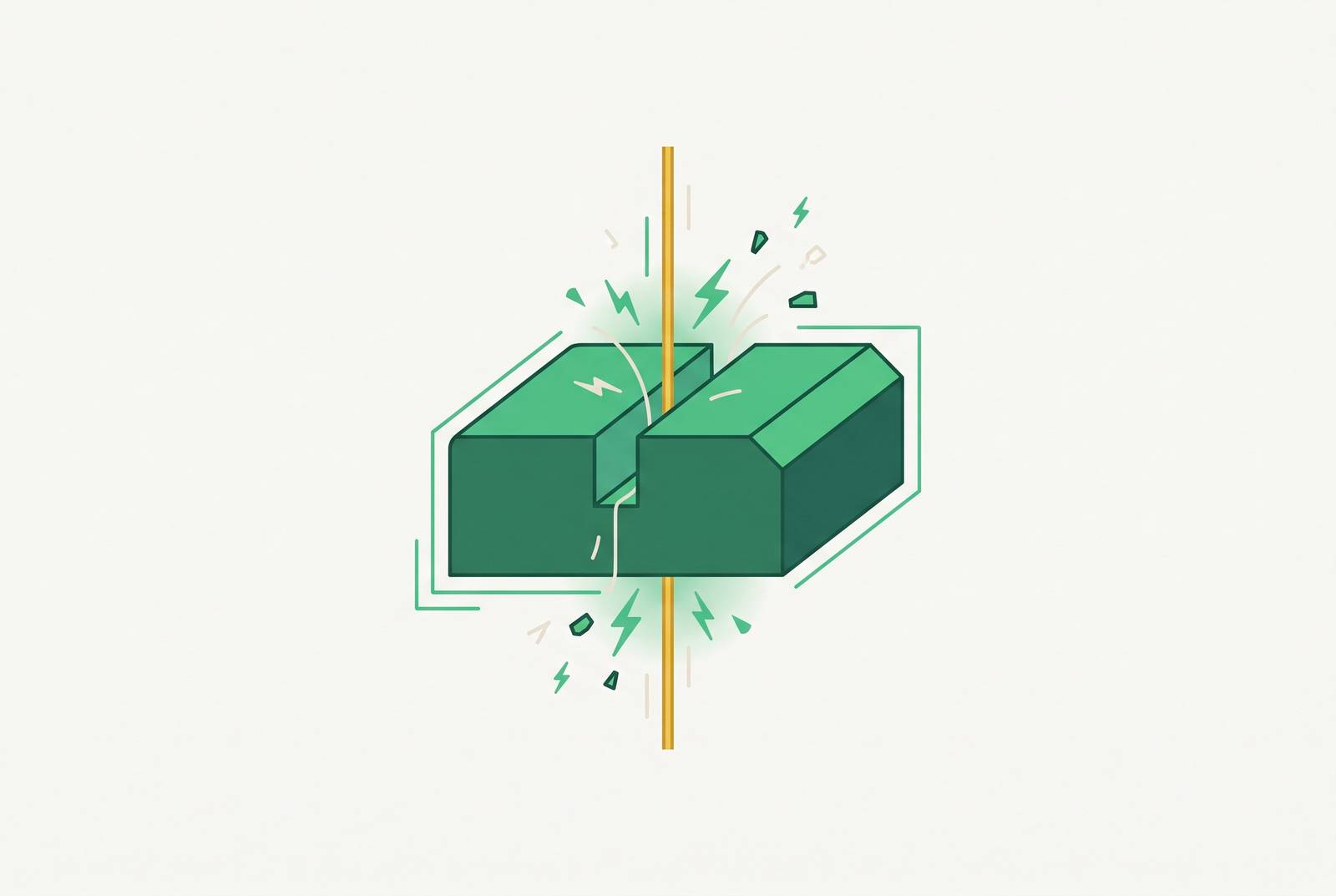
The wire itself never contacts the workpiece. A spark gap, held at roughly 0.01 to 0.05 mm, is between wire and metal, submerged in deionized water that keeps the discharges consistent xmake.com. That gap, not the wire diameter alone, is what actually sets the kerf width, and kerf width is what determines positional accuracy xmake.com. Miss that detail and you'll misjudge what the machine can actually deliver.
A single rough pass moves material fast. It also leaves a wider heat-affected zone and a coarse finish, fine for knocking down stock but nowhere near good enough for the final dimensions on a die component. Getting to final tolerance means skim cuts: semi-finish and finish passes that each remove less material than the last, tightening the spark gap and thinning the recast layer as they go. Three passes bring tool steel down to Ra 0.4 to 0.6 µm xmake.com. Add a fourth pass under favorable conditions and that number drops to Ra 0.2 to 0.3 µm xmake.com.
None of this is free. Multi-pass sequences roughly double machining time, and that's the tradeoff engineers need to internalize: extra passes aren't a capability question, they're a time and budget question xmake.com. Specify a tight tolerance without accounting for the passes it demands, and you've quietly written a multi-pass job into the drawing without budgeting the hours for it.
Machine hardware sets an outer limit, though it doesn't guarantee anything on its own. GF Machining Solutions' AgieCharmilles CUT P Pro series, for instance, is rated to 2 µm accuracy, a floor that a given part may or may not reach depending on material, geometry, and pass strategy xmake.com. That rating is a floor. Whether a given part actually reaches it depends on the material, the geometry, and the pass strategy applied to it xmake.com.
Achievable tolerance by material and the source of the numbers
Achievable tolerance is a range. It's a range, and that range moves with a material's conductivity, its thermal behavior, and its hardness. Treating tolerance as material-agnostic is where a lot of drawings go wrong before the part ever reaches the shop floor.
Tool steels are the backbone of die work, and they don't all behave the same way under the wire. D2 at 60+ HRC is comfortably within wire EDM's capability too precisemach.com. A die insert with a narrow slot held to ±0.003 mm positional tolerance counts as a routine job. M2 is the outlier among the three xmake.com. Its tungsten and molybdenum content cuts electrical conductivity, which slows the cut rate and raises the odds of wire breakage, so while the achievable tolerance stays roughly in line with the others, the cost and time per feature climb.
Tungsten carbide is a different case. Conventional machining destroys carbide tooling before it can finish a cut, which makes wire EDM the primary practical option for carbide die components. That capability comes at a price: carbide cut to tight tolerance runs substantially more expensive than tool steel at the same tolerance, because a slower cut speed stacks on top of the extra skim passes tight tolerance already demands.
Stainless steel, whether 304, 316, or 17-4 PH, cuts more slowly than carbon steel because of lower thermal conductivity, and runs a ±0.005 to ±0.01 mm tolerance range. Austenitic grades cut cleanly. PH grades tend to leave a good surface finish behind. Titanium, specifically Ti-6Al-4V, needs careful flushing to keep the recast layer from building up, since it's a reactive metal, and it holds to a similar ±0.005 to ±0.01 mm range. It appears less often in die work proper, but it's relevant wherever aerospace forming tools enter the picture.
It's context here. H13 (44–52 HRC) is the easiest tool steel to EDM, offering good conductivity, stable spark, and low wire breakage, with achievable tolerance in the ±0.003–±0.008 mm range per S4 (precisemach.com). Wire EDM is rarely cost-optimal for aluminum die components, as CNC is faster, and this is noted as context only, not a primary recommendation.
Surface finish ranges by pass strategy and their meaning for die function
Surface finish on a die component isn't a cosmetic spec. It governs punch-to-die clearance behavior, resistance to galling on sliding fits, how well a fluid-form tool seals, and fatigue life on any feature under repeated load. Get the finish wrong on the wrong zone, and the die wears out early or starts binding.
On tool steel, a three-pass sequence, rough, semi-finish, skim, is Ra 0.4 to 0.6 µm, which is roughly on par with precision surface grinding and covers most sliding fits and stamping die profiles xmake.com. Push to a four-pass skim sequence on materials that cooperate, and finish drops to Ra 0.2 to 0.3 µm, tight enough for sealing surfaces and precision tooling without needing a secondary grinding operation.
Some machines push past that without any extra step. A Fanuc Robocut 1IC fitted with a MicroFinish power supply reaches 6 micro-inches Ra straight off the wire, no secondary finishing pass required jennisoncorp.com. A grinding operation should not be assumed a foregone conclusion given that fact. It might not be.
The practical move on a die drawing is zoning the finish callout rather than applying one number across the whole part. Cutting profile, clearance faces, and non-functional surfaces don't need the same finish, and specifying one tight number globally just drives cost onto surfaces that will never notice the difference.
|The recast layer: its thickness and its significance for die components
Every spark in the cutting zone melts a tiny volume of the workpiece. Most of it gets flushed away by the dielectric, but some resolidifies on the cut surface before it can be carried off, leaving behind a thin band of altered microstructure called the recast layer. It's a byproduct of the process itself, not a defect from a bad setup, though how thick it gets is very much a function of setup.
Discharge energy and pass count drive that thickness directly. Lower energy settings and more skim passes thin it out; an aggressive rough pass leaves it thicker. A 2025 peer-reviewed study on GH3536 superalloy found that a 50 µs pulse width produced a recast layer averaging around 14 µm thick, and traced fatigue cracks back to microcracks and pores inside that recast layer, with parts in high-stress regions failing before hitting the target cycle count.
Die inserts mostly see compressive and shear loads, and the recast layer tolerates that kind of loading well enough to leave alone. Fatigue-critical features like thin punch tips under high-cycle stamping loads, forming tools taking repeated bending, stainless steel parts where aggressive power settings raise the risk of micro-cracking, and any aerospace or medical tooling carrying an explicit surface integrity spec are exceptions. In those cases, the recast layer needs to come off, whether through light polishing, light grinding, or a final low-energy skim pass that removes it without adding a separate operation to the routing.
None of that happens automatically. If a drawing doesn't call out recast layer requirements, most shops default to whatever cut sequence is most economical, and that sequence usually isn't the one that addresses recast.
DFM decisions that determine whether the tolerance callout on a die drawing is achievable
Internal corner radius trips up more die drawings than almost anything else. Wire EDM can't produce a truly sharp internal corner, full stop, because the minimum radius it can cut is set by the wire's diameter. A drawing calling for a sharp internal corner paired with a ±0.003 mm positional tolerance is contradicting itself before it even reaches the shop floor: either the geometry gives or the shop flags it before cutting starts. The fix is straightforward. State the minimum achievable radius on the drawing instead of implying a sharp corner, and the tolerance callout stays intact and enforceable.
Wall thickness and depth carry their own limits. Keep walls above 0.8 mm; go thinner and flushing turns inconsistent, which drags dimensional stability down with it xmake.com. Depth matters too, relative to wall thickness, and any feature pushing past roughly 100 mm deep is worth a direct conversation with the shop before it goes on the drawing at all.
Tolerance zoning is probably the single highest-leverage call an engineer makes on a die drawing. GD&T is the tool for sorting that out: identify which features drive punch-to-die clearance, which drive part location, and which are just clearance surfaces with no functional role, then tolerance each one accordingly. Standard features hold ±0.01 mm without needing a multi-pass sequence at all. Save ±0.005 mm or tighter for the handful of features where that precision actually changes how the die performs.
Heat treatment sequencing deserves its own line of attention. Rough EDM ahead of hardening clears the bulk stock while the material's still workable, and finish EDM after hardening captures the final dimensions in the hardened state, which is what keeps post-hardening distortion out of the functional geometry. If a supplier proposes skipping the rough EDM step before heat treat, that's a fair moment to ask for their distortion data on comparable parts before signing off on the deviation.
Wire selection affects cut speed and achievable feature size. Brass wire covers most jobs, and zinc-coated or diffusion-annealed wire pushes cut speed up on production runs. For deep, narrow slots or small-radius features common in die inserts, a smaller-diameter wire with higher tensile strength, molybdenum or tungsten, improves accuracy. M2 tool steel above a moderate thickness benefits from coated wire too, since it cuts down the breakage rate that M2's lower conductivity tends to cause. A global tight tolerance callout across all features of a Wire EDM die insert costs far more than selective tolerance callouts on functional surfaces only. The recommended sequence is stress relief, followed by rough Wire EDM, then hardening, then finish Wire EDM.
|Choosing between Wire EDM, CNC, grinding, and a combined sequence
Wire EDM earns its keep over grinding on complex internal profiles that a grinding wheel simply can't reach, on fully enclosed profiles, and on small-quantity runs where setting up a grinding operation costs more than the part count justifies. CNC takes over where it's genuinely faster and cheaper: aluminum die components, bulk stock removal ahead of an EDM finishing pass, and anything non-conductive, ceramics, plastics, composites, that wire EDM can't cut at all.
Most real die assemblies don't sit neatly in one category. Progressive die sets and multi-component die assemblies routinely carry features that call for all three processes at once, and no single process covers the full bill of materials. That reframes the whole question.
Sourcing follows from that directly. Consolidating the full die component BOM with one partner capable of running all of those processes closes that gap, keeping inspection accountability in a single place instead of scattered across separate vendors. The engineering implication is that the process selection decision is not Wire EDM vs. CNC vs. grinding but which surfaces get which process and in what sequence, making it a multi-process BOM problem rather than a single-process selection problem.
File preparation and drawing requirements that determine whether a Wire EDM quote reflects the actual part
Everything downstream starts with the file. A wire EDM programmer works from either a 2D DXF or a 3D STEP file, and STEP is the stronger choice for capturing full geometry, while DXF suits straightforward 2D profile work. Send the wrong format, or a file with gaps in it, and the quote that comes back is quoting a part that isn't quite the one on the drawing.
Open contours are the most common failure mode: profile lines that don't fully join leave the programmer guessing where the cut path is actually supposed to close. That guess, however reasonable, is still a guess, and it's exactly the kind of gap that turns a clean tolerance callout into a coin flip once the file reaches the floor.