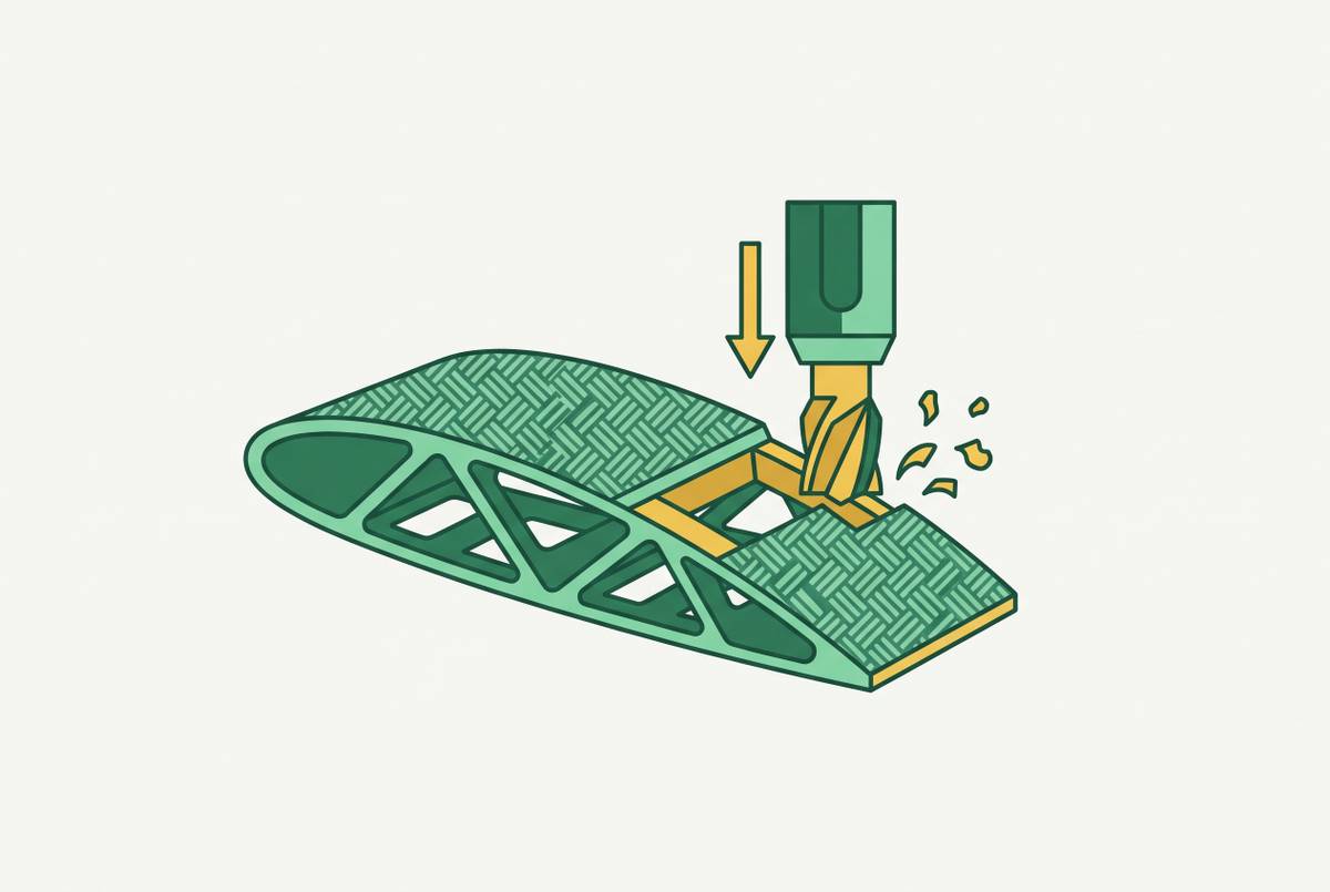
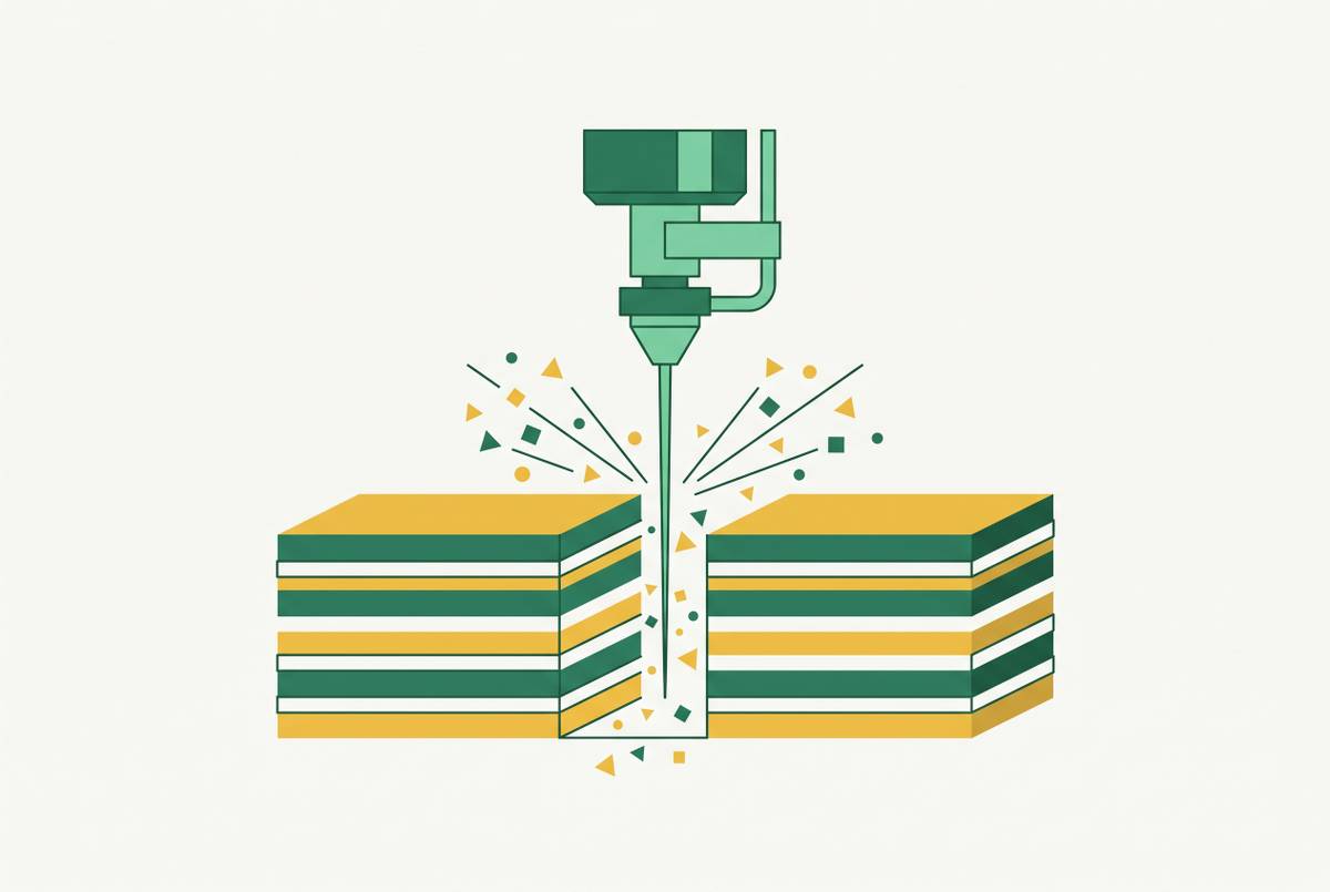
Urethane Overmolding and Insert Casting for Multi-Material Prototypes
Urethane casting methods let engineers test multi-material bonds before expensive tooling.
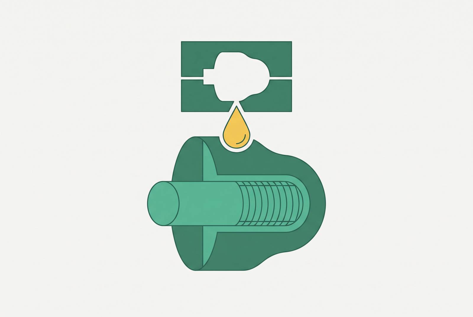
A prototype that pairs a rigid frame with a soft grip or a sealed gasket puts a hardware team in a tight spot. If you wait for steel injection mold tooling, the schedule stalls for weeks while tens of thousands of dollars go into a mold that can't yet account for design changes. If you snap together mismatched standalone parts instead, the test no longer measures what the production part will actually do. Urethane overmolding and insert casting exist to close that gap: they let an engineer build a part that behaves like the finished, multi-material product, well before any hard tooling gets cut.
3D printing looks like an obvious shortcut around this problem, and in a narrow sense it is. What they cannot do reliably is produce the kind of chemically bonded interface that overmolding produces in production. Printed interfaces are typically weaker than the chemically bonded interface overmolding produces. So a printed multi-material part might look right on a shelf, but it will tell an engineer the wrong thing about peel strength, grip durability, or seal integrity.
This matters because what you decide at this prototype stage carries real weight. Skipping proper validation of how the soft and rigid materials interact, how the part feels in a hand, or whether an insert stays put under load means the first real test of those questions happens after the steel mold is already cut and paid for. Vacuum casting with urethane was built specifically to simulate an injection-molded part before that commitment, combining flexible and rigid materials through overmolding or adding metal components through insert molding, at a fraction of what hard tooling costs.
Sequential casting, insert encapsulation, and separate-part assembly
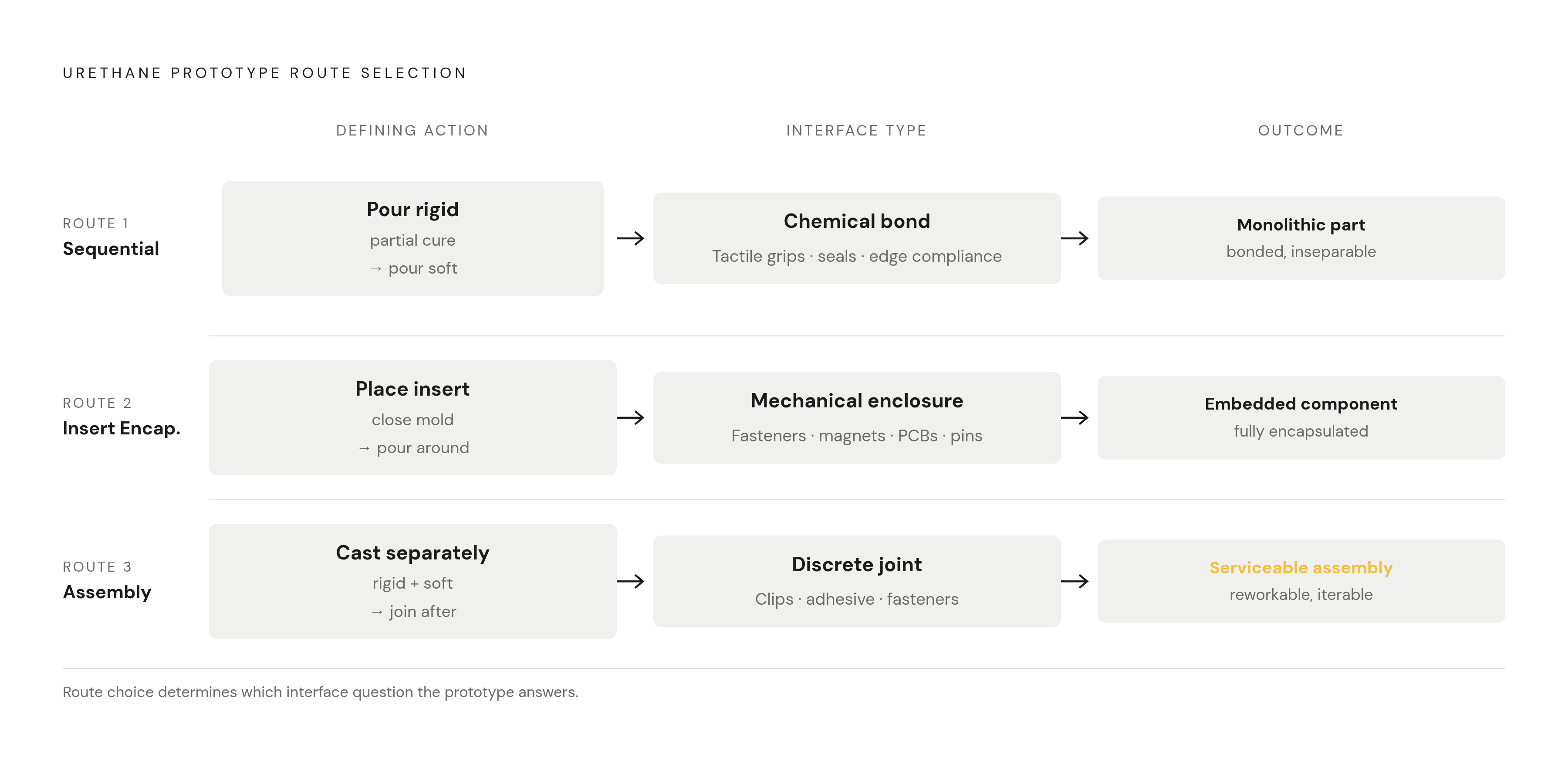
Urethane prototyping splits into three distinct process routes, and if you pick the wrong one for a given interface, you get a part that answers the wrong question entirely. Each route suits a different kind of interface, and the choice should follow from what the engineer actually needs to test, not from habit or convenience.
Sequential casting is the method built for a soft material fused directly onto a rigid one. A rigid urethane resin gets poured first, forming the substrate or core of the part. Once that region has partially or fully cured, a second, softer urethane goes into the same mold to form the overmolded features. The two materials end up chemically bonded rather than mechanically joined, forming a single, seamless, monolithic prototype. Timing drives everything here: the surface state of that first pour, whether it's fully cured, still partially green, or contaminated by release agent or skin oil, controls how well the second resin wets the surface and how strong the resulting bond turns out to be. This route fits soft-over-rigid regions directly: tactile grips, button actuation, edge compliance, gasket-like seals where the transition between materials needs to look and feel continuous. A bond can look fine from the outside but have incomplete coverage, contamination, or trapped air underneath. A sectioned sacrificial sample, cut open and inspected, confirms what a surface check alone cannot.
Insert encapsulation, or insert casting, solves a different problem: getting a rigid or functional component fully embedded inside cast urethane. The insert goes into the mold before it closes. Two polyurethane compounds then get poured in, the liquid resin flows around the captured insert, the resin solidifies and bonds tightly to it, and once the mold opens, the insert sits fully encapsulated as part of one unified piece. Inserts here can be threaded fasteners, magnets, pins, rigid carriers, PCBs, or any previously made component that needs to live inside the part. The risks are mechanical rather than chemical: a floating insert can shift mid-fill, a poorly sealed insert face can leak resin onto a surface that needs to stay clean, and sharp insert edges concentrate stress in the cured urethane around them. Locating fixtures or molded locators keep the insert positioned correctly. Retention needs testing in whatever direction the part will actually see load, whether that's pull, torque, bending, or pressure, rather than just confirming by eye that the insert is sealed in.
The third route forgoes integration. Rigid and soft components get cast independently, then assembled afterward with clips, adhesive, fasteners, or a replaceable seal, matching whatever architecture the production part will actually use rather than forcing a one-piece casting. This approach lets an engineer swap a material or a geometry variant on one sub-part without remaking the whole assembly, and it surfaces stack-up and serviceability questions that an integrated casting would simply hide. It fits assemblies built around a serviceable seal, a sub-region still under active design iteration, or a production design that was never going to use overmolding.
None of these three routes should be mistaken for a full stand-in for production overmolding. They don't validate the exact adhesion behavior of a thermoplastic overmold or guarantee the polyurethane chosen for prototyping matches the target production polymer's creep, tear, fatigue, and chemical resistance. A urethane picked to screen one property, hardness or compliance, can diverge from the production material on everything else. Knowing that limit upfront keeps an engineer from over-reading what the prototype proves.
DFM rules that determine whether a multi-material urethane part bonds, releases, and holds tolerance
Design choices that barely register in a single-material part can turn into failure points once you add two materials and a mold release step. Wall thickness, corner radii, how an interface terminates, draft angle: each one decides whether the part bonds cleanly, demolds without damage, and lands within tolerance.
Wall thickness governs flow, cure behavior, and interface stress all at once, with a minimum of 1.5 mm for overmolded features, since sections significantly thicker than this generate interface stress from differential cure rates and thermal history. The substrate also needs to run noticeably thicker than the overmold layer sitting on it: a thin rigid substrate simply doesn't have the stiffness to resist the shrinkage force of a thick overmold skin as it cures.
A clean-looking transition between materials says nothing about how well that interface resists peel. An overmold surface can look seamless and still separate under load if nothing beyond surface bonding holds it there. If the soft region carries any real load, the design needs mechanical retention built in: holes, dovetails, ribs, wraparound edges, or a step feature, beyond adhesion alone. A step or groove cut 0.3 to 0.5 mm deep at the point where the overmold terminates tucks the edge in and stops peel from starting there in the first place. Wherever the geometry allows it, orient these interlocks so that normal service loads push the interface into compression or shear rather than pulling it apart in peel, since peel is the weakest mode for any bonded joint. These interlocks bring their own failure modes, too: a thin rigid web around an interlock can crack, a narrow key feature can trap air and fail to fill completely, and an undercut that helps retention can make the part harder to pull from the mold. You need to review flow access and mold release together, because they are not separate concerns.
Draft isn't a requirement the way it is in injection molding. Flexible silicone molds can flex enough to take undercuts, snap-fit features, and internal channels that would need side-actions in a hard steel tool. Add draft anyway, because it extends how many cycles a mold survives and makes extraction easier, and if the part is headed toward injection molding later, you need this to prove the geometry works in both processes. For ribs, keep height to roughly three times the rib's thickness at most, and reach for several shorter ribs instead of one tall one, since a tall thin rib is exactly the geometry that cracks or fails to fill.
Tolerance expectations need to get set before the design work starts, not after a part comes back short. Standard dimensional accuracy for overmolding and insert molding runs at ±0.2%, with a lower limit of ±0.2 mm, by YellowHammer's published analysis, and no tighter-spec SLA-master option appears in YellowHammer's own specifications. Shrinkage typically appears in the part as a small positive offset, so the smart move is planning for it at the critical mating features in the design itself, rather than trying to fix it afterward in post-processing.
Insert casting carries its own additional DFM checklist. Insert material, finish, dimensions, orientation, and any coating or release residue that has to stay off the part all need to go to the supplier before quoting, since every one of those affects encapsulation quality and how well the insert holds once it's embedded. If a threaded insert is going to see repeated use, specify the installation torque and the expected cycle count, rather than treating one successful test assembly as proof the design works.
The silicone mold master pattern workflow
Every cast part traces back to one master pattern, and that master controls surface quality, dimensional accuracy, and how faithfully the final part reflects the original CAD design. It's also the point in the whole process where an engineer's design decisions carry the most weight, since every flaw or refinement built into the master gets copied into every part cast from it.
The standard path runs in a clear sequence. An SLA or FDM 3D print forms the master, and you then hand-finish and polish it to the surface quality the final parts need. RTV silicone gets poured around that master inside a mold frame, suspended so the silicone fully surrounds it. After several hours of cure time, you cut the mold precisely along a parting line, take the master out, and add a gating and venting system so resin can flow in and trapped air can escape during casting. Every texture, edge, and surface detail on that master transfers directly onto every single copy cast from the mold. A poorly finished master doesn't just produce one bad part; it multiplies the same defect across the entire run. For geometries that need tighter tolerances than SLA can deliver, or for materials that don't print cleanly, a CNC-machined master takes the place of the printed one.
The flexible nature of RTV silicone is what enables undercut geometries and eliminates the side-action complexity that injection molds require. Because the mold itself can flex during demolding, it accommodates undercut geometry, snap-fit features, and internal channels without needing the side-actions a steel injection mold would require for the same shapes. That flexibility comes at a cost in longevity: a single RTV silicone mold only yields a limited number of casts before it starts to degrade, though switching to HTV silicone or rubber extends that life considerably for teams that need higher volumes.
Casting itself follows a repeatable cycle. Two-part liquid polyurethane gets mixed and poured into the mold cavity, the filled mold goes into a vacuum chamber to pull out trapped air bubbles before the resin gels, and once curing finishes, the part comes out and the cycle starts again for the next copy.
What an engineer sends in determines how smoothly all of this runs. A 3D CAD file of the master pattern is the baseline requirement every time. For insert casting, the insert's dimensions, orientation, and material need to go along with that model. For sequential casting, the parting line between the rigid and soft material regions needs to be called out explicitly in the drawing or model itself, not left for the mold maker to guess. Getting these details right before a quote goes out saves a round-trip later, when the mold is already cut and a missing detail forces a redo.
Specifying dual-durometer design in practice
Durometer gets treated too often as if it were a fixed material property, a single number stamped on a datasheet. In practice it's a design range, shaped as much by geometry as by the resin itself, and specifying it as a bare number without the geometry behind it produces a prototype that doesn't actually answer the question it was built to answer.
What an engineer is usually testing, whether it's button actuation, grip comfort, edge compliance, or local sealing pressure, depends on more than hardness alone. Section thickness, the support structure underneath, strain rate, temperature, and how fully the material has cured together determine how that region actually feels and performs. If a Shore A 40 overmold sits on a thin, unsupported wall, it feels noticeably softer than that same material backed by a thick, rigid substrate. The substrate geometry is as much a part of the compliance specification as the durometer number is. Specifying hardness alone and leaving the backing structure unspecified leaves the actual feel of the part undefined.
Cast urethane covers a wide span of this range. Flexible urethane resins run from Shore A 20 up to Shore A 95, while rigid resins span Shore D 75 to 85, so you get everything from soft rubber through hard engineering plastic in one material family. That range gives you room to match a prototype's feel closely to a target production material without switching processes. A common functional pairing puts a rigid ABS-like core, around Shore D 78, together with a rubber-like overmold in the Shore A 40 to 60 range, the combination typically used for tool grips where a hard internal frame needs a soft, comfortable outer surface.
Specifying dual-durometer correctly means giving a supplier both numbers and the geometry that supports them: the hardness for each region, the substrate thickness backing the softer material, and the interface detail (step, groove, or mechanical lock) that holds the two together under load, since the durometer spec alone, without that geometry, is incomplete.