Abrasive Waterjet Cutting for Thick-Section and Composite Parts
Cold-water erosion avoids heat damage that degrades thick metals and composite edges.
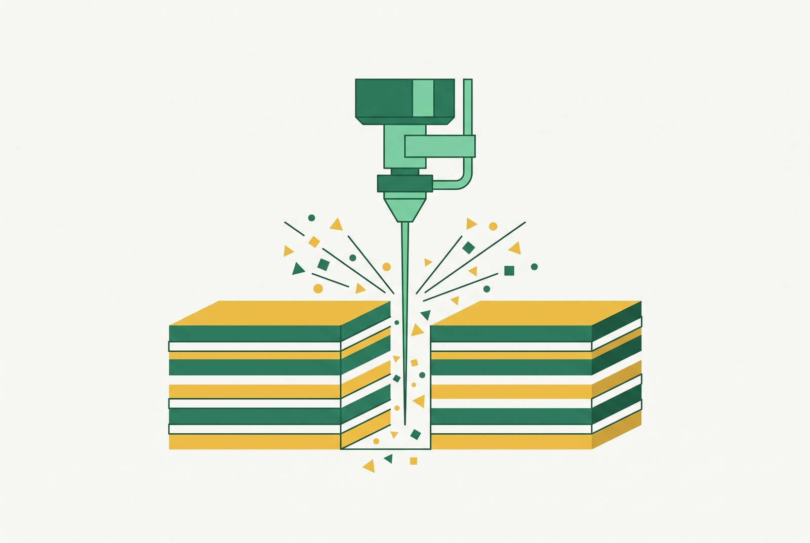
Abrasive waterjet cutting removes material by erosion, not heat. A supersonic stream of water mixed with garnet, or sometimes aluminum oxide, wears away the workpiece the way a river wears away rock, just compressed into seconds instead of centuries. That single fact, no heat, is the reason AWJ holds up where plasma, oxyfuel, and laser cutting fall short on thick metal and composite laminates.
Thermal cutting methods leave behind a heat-affected zone at the cut edge. That band of material gets hardened, sensitized, or microcracked by the temperature spike, and it doesn't behave like the rest of the part anymore. Apex Engineered Products lays out the stakes for corrosive service: pitting, crevice corrosion, and stress corrosion cracking all start at the HAZ and at microcracks when the part sits in an aggressive chemical environment. Abrasive waterjet skips that problem. It delivers the base metal's native corrosion resistance all the way to the cut line, because there's no thermal event to change the metal's structure.
Composite laminates face a parallel problem, just with resin instead of metal grain structure. Heat chars the resin matrix and weakens the bond between fiber and matrix, and a laser or hot wire cutting a carbon fiber panel will leave scorched, degraded edges behind. Erosive cutting never introduces that heat, so the matrix stays intact right up to the edge. Flow Waterjet describes the resulting edge on composites as satin-smooth, free of frayed or delaminated areas, a direct result of erosion removing material instead of friction or shearing tearing it away.
The cold mechanism also means AWJ doesn't care what it's cutting. Steel, titanium, nickel alloys, carbon fiber, fiberglass, rubber, PTFE, ceramic: the same erosion process handles all of them without a process changeover. That material independence matters for everything that follows in this piece, because it means the physics discussed here apply whether the part on the table is a two-inch titanium plate or a quarter-inch CFRP panel.
How the jet erodes thick sections
The jet carries its cutting power as kinetic energy, and that energy doesn't survive the trip through the material unchanged. As the stream penetrates deeper into a thick section, it loses energy to the cut wall, and that loss is what produces taper, waviness on the lower surface, and the V-shaped kerf that defines AWJ's main geometric limitation.
Picture the jet entering the top of the plate at full force and slowing as it works downward. The stream is strongest where it enters and weakest by the time it reaches the bottom of a thick section. That energy gradient is the physical root of kerf taper: the cut runs wider at the entry face than at the exit face, because the jet at the top has more erosive power to spread and more time to act before it's spent.
Taper is a built-in consequence of how energy dissipates through a cut, present to some degree in every job AWJ runs. The deeper the section, the steeper the gradient becomes: the jet deflects more, the bottom of the kerf lags further behind the top, and the lower cut face shows more waviness. Research on graphite-epoxy composites backs this up directly, finding that taper angle responds to jet pressure, traverse speed, abrasive feed rate, and cutting head size. Those four variables are the levers that control the gradient, and they reappear through the rest of this piece because they're the same levers that control everything else about cut quality.
A reasonable objection follows from all this: if taper is baked into the physics, how can AWJ claim to be a precision process for thick parts? Taper is managed. Tilting the cutting head to compensate for the angle, slowing the feed rate, and tuning abrasive flow and pressure together bring taper within acceptable bounds for a given thickness and tolerance. The energy gradient sets the boundary conditions for what the process can do. It doesn't rule the process out.
Composite laminates' different failure mode
Thick metal parts fail an AWJ cut through taper and surface waviness. Carbon fiber laminates fail a different way: they delaminate, the plies separating from each other rather than the surface roughening or the kerf widening unevenly. The highest risk for that failure doesn't happen during the steady cutting pass. It happens at the pierce, the moment the jet first punches into raw laminate, when hydraulic pressure slams into the material before the abrasive stream has started its erosive work.
Mechanical cutting tools like router bits and diamond saws cause a related but distinct problem: fiber pull-out, where friction and shearing forces drag fibers out of the matrix rather than cutting them cleanly. AWJ's contact force, both lateral and vertical, stays low enough that it avoids that failure mode. Flow Waterjet lists no delamination, no whiskers, and no fiber pull during cutting among the process's core benefits on composite materials, and that list reflects a cutting mechanism that erodes material cleanly rather than tearing it loose.
Glass fiber composites handle interlaminar stress better than carbon fiber does, giving them more margin before delamination becomes a concern. But that margin isn't unlimited. Laminate thickness and weave density both still need to be built into the process parameters, or a glass fiber panel can delaminate just as a CFRP panel would.
The pierce event is where laminates are most exposed, and it's worth understanding why. Before the abrasive jet establishes its cutting action, the raw water stream hits the laminate surface at full hydraulic pressure, and that shock event differs from the steady erosive cutting that follows. Research on graphite-epoxy composites confirms the payoff when this is managed well: AWJ produces high cut quality on composite panels and I-beam stringers with no rework required, where conventional extrusion milling left edges that needed secondary finishing. Boeing's patent on compact waterjet catchers backs this up for aerospace structure specifically, naming AWJ an effective tool for cutting graphite-epoxy panels and I-beam stringers for airplane components, precisely because the cut quality removes the edge rework that extrusion milling demands. The pierce event is also where dry composite machining creates a separate hazard: fine carbon particulate dust. Cutting underwater or in a flooded bed suppresses that dust, capturing the particulate that a dry process would release into the air.
Process parameters that control cut quality in practice
Cut quality depends on the interaction of several settings, not any single one. Feed rate, abrasive mass flow, standoff distance, and jet pressure all interact. The right balance among them shifts with material thickness and composition.
Feed rate, or traverse speed, carries the most weight of the four. Slowing the jet down means it spends more time eroding each unit of material, which cuts down on taper and improves the finish on the lower surface. Speed the traverse up and taper grows, while delamination risk on composites climbs as well. Research on low-pressure AWJ confirms the pattern holds broadly: depth of penetration falls, and both surface roughness and kerf taper ratio rise, as traverse rate increases. That relationship is visible consistently across different materials, not just one.
Abrasive mass flow sets how efficiently the jet erodes material. Starve the jet of garnet and cutting power drops. Flood it with too much abrasive and the mixing tube can clog, slowing the jet down. The window between those two failure points narrows as sections get thicker and materials get harder, so the abrasive flow that works for a half-inch aluminum plate won't necessarily work for a two-inch titanium one.
Standoff distance, the gap between the nozzle and the workpiece, is just a few millimeters in practice, a geometry confirmed in one manufacturer's waterjet cutting patent. Too much standoff lets the jet spread out before it ever touches the material, widening the kerf and worsening taper. Too little standoff risks splash-back damaging the nozzle itself.
Jet pressure raises cutting power and lets you run a faster traverse at the same quality level, but it also raises the hydraulic shock at the pierce point, the same shock that drives delamination risk in composites. Pressure management at pierce is a separate problem from pressure management during the steady cutting pass, and treating them as the same setting is a common source of avoidable damage.
These tradeoffs get formalized into quality tiers, labeled Q1 through Q5. Q1 is a separation cut: fastest traverse, roughest surface, most taper, the setting used when a part just needs to be freed from stock and edge finish doesn't matter. Q5 sits at the other end: slowest traverse, smoothest surface, least taper, reserved for finishing passes where edge quality is the priority. Q3 is the standard setting for most production parts, the middle ground that balances speed against quality for everyday work.
The condition of the nozzle itself is one more variable that affects cut quality: a worn mixing tube widens and distorts the jet stream, and that distortion increases kerf width in ways that are hard to predict or compensate for. Nozzle replacement cadence functions as a quality control variable in its own right.
DFM decisions that determine whether AWJ delivers usable parts
The decisions that most affect an AWJ part's outcome get made in the CAD file, long before the machine ever starts cutting. Pierce placement, lead-in path, minimum feature size relative to kerf width, and laminate fiber orientation relative to cut direction all shape what the finished part looks like, and all of them are design choices, not machine settings.
Pierce placement carries the highest stakes for delamination risk, discussed above in the context of composite laminates. Piercing directly on a finished edge puts that hydraulic shock exactly where the part can least afford it. Moving the pierce point off the part boundary, onto sacrificial material or into a scrap zone, removes that water-hammer stress from the finished geometry. That's a decision made in the drawing, not adjusted on the shop floor.
Lead-in geometry works alongside pierce placement to solve the same problem. An extended lead-in path gives the jet room to stabilize after the pierce, absorbing the shock event before the stream ever reaches the part's actual contour. By the time the cut engages the finished edge, the jet has settled into steady-state erosion rather than still recovering from the initial impact.
Minimum feature size comes directly out of kerf width. Any feature narrower than the kerf simply can't be cut, full stop, and features only slightly wider than the kerf will show taper effects out of proportion to their size. If you're designing inside radii and slot widths, you need to size those features against the actual mixing tube diameter the job will run, not against a generic rule of thumb.
Laminate orientation governs edge quality on CFRP specifically. The angle between the cut path and the dominant fiber direction changes how cleanly the jet erodes through the material. Cutting parallel to a fiber tow risks running the jet straight along the fiber-matrix interface, the weakest plane in the laminate. Cutting across the fibers at an angle spreads the erosive work across more fiber ends at once, and that produces a cleaner edge than a parallel cut will.
Tolerance strategy closes out the DFM picture. AWJ holds near-net geometry in a single pass for most applications, often removing the need for any secondary finishing. But where a feature demands tighter tolerance than the process can hold at a given thickness, the answer is to use AWJ as a roughing operation and finish the feature on a CNC mill. That's a planned two-step sequence, built into the part's process plan from the start.
File format rounds out the practical side of design handoff. Industrial waterjet shops work from DXF, DWG, IGES, and STEP as standard geometry formats, with PDF accepted only as a reference document rather than something CAM software can cut from. DXF comes up most often, and clean 2D geometry in that format lets the program move straight into CAM without redrawing.
Where AWJ fits in a multi-process mechanical BOM
For parts that need tighter tolerances than AWJ can hold on its own, the right move is to plan AWJ as the first operation, the one that strips roughing time out of a downstream CNC cycle before the mill ever touches the part. The real risk occurs when that two-step sequence gets split across separate vendors.
AWJ removes the bulk of material from a thick blank in a single pass, with no tooling required to make it happen. Apex Engineered Products documents the payoff on expensive alloys specifically: near-net waterjet cutting on materials like nickel-based CRA, zirconium, or tantalum cuts down the volume of material a mill has to remove afterward. Both the expensive raw material and the expensive CNC machining time shrink as a result.
Keeping both operations under one roof changes the handoff between them. When the same shop runs the AWJ cut and the CNC finish, that handoff stays internal: no purchase order between steps, no re-fixture quote, no scheduling gap between the blank coming off the waterjet table and going into the mill. Splitting those operations across two vendors adds friction at each transition: the second vendor has to re-quote the finish work against a blank they didn't cut themselves, re-fixture the part without having designed the original hold strategy, and absorb schedule risk at every handoff between the two shops.
AWJ also carries no physical tooling or die fabrication, so there's no lead time tied to building hard tooling before the first part can run. The same CAM program and cutting parameters apply across material grades, so a first article can move to production volume without a re-qualification cycle in between.
That same material independence pays off across a mixed-material bill of materials. A single CAD file can drive cuts across steel, titanium, aluminum, CFRP, and PTFE on the same table, which makes the case for consolidating an entire BOM at one capable source rather than routing each material to a different specialist. Flow Waterjet points to single-pass cutting across a range of material thicknesses, omni-directional cutting capability, and minimal kerf width as the properties behind that near-net output and reduced scrap, savings that matter most on expensive composite panels and alloy stock.
Gaskets, custom seals, and elastomeric parts follow the same logic. Waterjet cuts rubber, PTFE, cork, and composite laminates to precise dimensional tolerances with no tooling changeover required between jobs, which makes it the natural companion process to machined metal hardware across a mixed-material assembly.
Sources
- abrasive waterjet machining: Topics by Science.gov
- Compact catcher for abrasive waterjets
- Water jet cutting device with improved part-holding device
- Evaluation of the Depth and Width of Cuts after Controlled-Depth Abrasive Water Jet Machining Using Low Pressure - PMC
- A Multi-Response Investigation of Abrasive Waterjet Machining Parameters on the Surface Integrity of Twinning-Induced Plasticity (TWIP) Steel