Electrochemical Machining for Complex Internal Cavity Parts
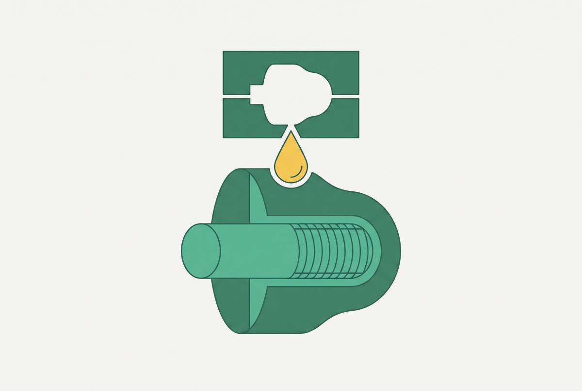
ECM dissolves metal to reach internal cavities conventional tools cannot.

Electrochemical machining (ECM) dissolves metal rather than cutting it, and that single difference is what lets it reach internal cavities, undercuts, and irregular profiles that conventional machining cannot physically enter. Understanding the mechanism behind that claim is the starting point for designing parts that use it correctly.
Why conventional machining fails at complex internal cavity geometry
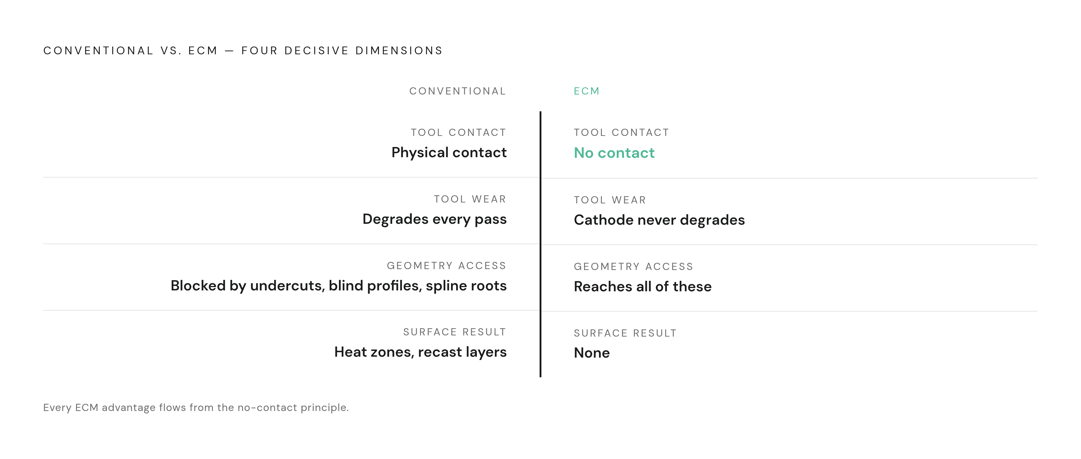
Conventional machining relies on a rotating cutter or a drill bit that has to enter a feature, pass through it, and exit the other side. That requirement sounds basic, but it quietly rules out an entire category of geometry. Undercuts, blind profiles, and intersecting internal passages break the entry-traverse-exit sequence completely, no matter how precisely a design model defines them. A tool-workpiece contact that cannot physically happen is a hard stop, not a tolerance problem or a cost problem.
Material compounds the issue. A 2026 review in the Journal of Alloys and Compounds points out that titanium alloys and similarly difficult-to-cut materials give conventional cutting trouble for reasons beyond shape alone: poor heat dissipation and poor machinability work against the tool even on geometry a cutter could otherwise reach.
Internal splines in high-hardness aero-mechanical transmission components show what this looks like in practice. Research notes that cutting this exact feature type with conventional methods wears out tools fast and stretches production cycles. The spline roots sit deep inside a bore, the material resists the cutter, and every pass accelerates tool degradation. Engineers can specify the feature on a drawing. The shop floor cannot produce it without compromising the geometry, burning through tooling, or accepting cycle times that make the part uneconomical.
How ECM removes material without touching it
The workpiece acts as the anode. A shaped cathode tool serves as the negative electrode. Pressurized electrolyte floods the gap between the two: it carries current across the gap and carries away the dissolved metal hydroxide as it forms. Material comes off the workpiece through an electrochemical reaction rather than a cutting force.
Because the cathode never touches the part, it never wears. A conventional cutting tool degrades with every pass through hard material, so a shop has to swap tools, recalibrate, and absorb the cost each time. An ECM cathode holds its geometry across an entire production run. Because of that, the economics of machining hard and exotic alloys change, since tool wear is normally the biggest cost driver there.
The machined shape comes out as the inverse of the cathode face. Tool geometry drives part geometry directly, so most of the engineering effort in ECM shifts away from fixturing and toward designing the cathode itself. Pulsed ECM (PECM) refines this further. PECM uses pulsed power along with tight control of the inter-electrode gap, so it localizes material removal more precisely than continuous ECM, and that matters most on features where field spread would otherwise blur a sharp profile edge into something rounder than intended.
The practical consequence runs through everything that follows: since the tool never makes contact, geometry that blocks a cutter stops being a limitation for ECM.
Why internal cavities specifically benefit from electrochemical dissolution
Non-contact removal paired with electrolyte that can be routed almost anywhere means ECM reaches internal features that defeat other processes outright: undercuts, blind profiles, intersecting passages, and spline roots that no cutter can enter and that spark erosion tools struggle to finish reliably at production scale.
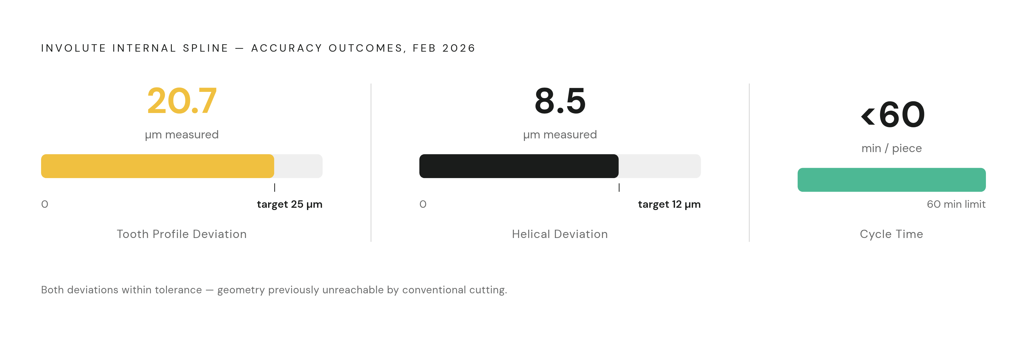
The February 2026 study on involute internal splines in semi-blind holes shows what that capability looks like when measured. ECM produced these features in high-hardness material with tooth profile deviation of 20.7 micrometers and helical deviation of 8.5 micrometers, both inside target accuracy, completed in under one hour per piece. That is a feature class that stops conventional cutting cold, machined to spec, in a timeframe a shop can plan around.
The hexagonal oil cavities found on the inner surface of hydrostatic bearings make a similar case from a different angle. The October 2025 study on this geometry describes it as a complex inner cavity curved surface structure that poses significant challenges to traditional machining, and uses ECM as the process that gets it done.
ECM's reach extends down to the miniature end of the scale too. IEEE-published research demonstrates machining micro features on the side wall of a micro hole, including reverse tapered holes, barrel-shape holes, and microgrooves inside holes, controlled through pulse conditions and custom electrode design. That pushes ECM's internal-cavity advantage into geometries too small for a cutting tool to approach.
Electrochemical deburring (ECD) extends the same physics into finishing work rather than primary shaping. ECD concentrates the electric field at burr locations inside intersecting holes and internal channels while the surrounding smooth surfaces stay below the threshold needed for dissolution to occur. That selectivity makes ECD useful on hydraulic valve components, fuel injector bodies, and precision fluid system parts, wherever mechanical deburring tools cannot physically reach the burr. ECM is also a way to clean up a cavity after another process leaves it rough.
Field spread in ECM and its limits on accuracy
ECM's electric field does not stop precisely at the edge of the cathode. It spreads through the electrolyte beyond the cathode footprint, and that spread rounds internal corners and lowers absolute dimensional accuracy compared to EDM. That is a real constraint, and acknowledging it directly is what lets an engineer design around it instead of discovering it after a part ships.
The hydrostatic bearing oil cavity study quantifies part of this sensitivity. Dimensional deviation shows a positive correlation with increasing voltage, and surface roughness follows a non-linear relationship as voltage changes. So you have to actively control ECM's process window during setup, not assume it behaves the same way across every part.
Field spread appears most visibly on features that demand sharp internal corners: spline roots, keyways, die cavities. These are exactly the details where ECM accuracy degrades the most, because the field physically cannot be confined as tightly as a focused spark. EDM's spark erosion stays localized in a way ECM's dissolution does not, which makes EDM the better fit for those specific corner details.
None of this makes ECM a weaker process overall. ECM produces surfaces free of heat-affected zones, recast layers, and microcracks, and that matters for turbine blades and medical implants, where any of those three defects can compromise fatigue life. The trade is real in both directions: ECM gives up some corner sharpness to deliver that surface integrity.
The resolution is to route by feature type rather than commit to one process out of habit. Smooth internal profiles, contoured cavities, intersecting passages, and burr-free internal channels favor ECM. Sharp-cornered internal forms may call for EDM on its own, or a hybrid sequence where ECM does the bulk removal and EDM finishes the corners.
Material conductivity and ECM's processing limits
ECM only works on electrically conductive materials, and this is a hard constraint rather than a preference a designer can work around with a different parameter set. Conductivity decides which components on a mixed-process bill of materials can even be candidates for ECM, before you ask any question about geometry or tolerance.
Within that constraint, ECM performs best on exactly the materials that make conventional cutting expensive: titanium aluminides, Inconel, Waspaloy, and high nickel, cobalt, and rhenium alloys. These alloys wear conventional tooling fastest, and they dominate aerospace and high-performance mechanical assemblies. ECM's material fit lines up closely with where the hardest machining problems already live. The February 2026 spline study works explicitly in high-hardness gear steel, a material where conventional cutting wears tools out fast. ECM removes that cost driver from the process entirely, since the cathode never contacts the part and never degrades from the hardness of the workpiece.
Non-conductive materials sit outside ECM's range. Carbon fiber composites, ceramics, and engineering plastics cannot be processed this way. Features made from those materials need CNC routing, abrasive waterjet cutting, or layup processes instead, on the same bill of materials as ECM parts.
For any assembly built from multiple materials, this conductivity filter decides which components route to ECM and which route elsewhere. That routing decision shapes how a hardware team structures its BOM and its vendor relationships from early in a program.
Design for manufacturability rules that govern ECM internal cavity work
ECM internal cavity geometry depends on three constraints that interact with each other: material conductivity, cathode accessibility, and electrolyte flow path. Skipping any one of them at the design stage turns into expensive rework once a part has already been quoted.
Conductivity needs confirmation at material selection, not at DFM review. The workpiece has to be electrically conductive, and catching a non-conductive material choice late in the process means the entire ECM plan gets scrapped and the part starts over with a different process.
Cathode design works in reverse from the final part geometry. The cathode itself needs excellent electrical conductivity, enough rigidity to withstand mechanical load and fluid pressure during machining, chemical inertness in the electrolyte, and a form that machines easily into the required shape. Any internal feature that cannot be mirrored into a cathode meeting all four of those properties is not producible by ECM, full stop on the geometry side.
Electrolyte flow paths need to be designed in from the start rather than assumed to work themselves out. A hydrostatic bearing study shows that the size of the cathode's liquid-through groove (LTG) directly controls flow rate, current density uniformity, and residual protrusion on the finished cavity. A designer, not the ECM shop, sets those parameters. A designer sets them the moment cavity geometry and access are specified on the drawing.
For blind and semi-blind internal passages, electrolyte entry and exit need to be built into the fixture or the part design from the outset. If flow cannot reach every part of the reaction zone, the dissolution process starves, and you see it show up as degraded surface quality and weaker dimensional control.
Involute splines carry their own version of this lesson. The February 2026 study first evaluated flow field orientation, then developed and validated three flow field optimization methods through simulation: a guided flow head, cathode working teeth, and a circular rectifier, each aimed at improving electrolyte distribution and stabilizing the spline ECM process. The optimal flow configuration was not obvious from the geometry alone. It took simulation to find.
PECM opens a further DFM opportunity. Because its tooling can be customized, PECM can machine multiple features in parallel rather than one at a time. A designer who plans for parallel feature machining from the start recovers cycle time that a single-feature, sequential ECM setup cannot reclaim later.
GD&T callouts on internal features feed straight into cathode engineering. Ambiguous tolerance or unclear feature orientation forces the cathode through repeated redesign, and that iteration is where non-recurring engineering cost builds up fastest.
Staging ECM into a prototyping and low-volume production workflow
ECM's tooling investment makes it a poor fit for first-article prototyping. A staged workflow, CNC or EDM for early validation and ECM once volume justifies it, captures ECM's advantages at the point in a program where they pay off, without forcing a team to pay ECM's costs before the design has settled.
CNC machining handles functional prototypes well. Its material versatility lets engineers validate form, fit, and function without committing to ECM tooling before the design is locked. That makes CNC the right first step for any internal cavity feature that will eventually move to ECM in production.
EDM bridges the gap for complex cavity details before a team commits to ECM. CNC can rough and semi-finish a cavity, sinker EDM can finish sharp corners and ribs, and the full assembly can be validated against form and function before cathode engineering ever begins.
ECM's non-recurring cost sits almost entirely in cathode development. Getting a cathode right takes multiple iterations of design and testing, and that investment only pays off once part volumes are high enough to spread the cost across. The shift from EDM to ECM is a volume threshold decision, driven by how many parts a program needs.
Once cathode tooling is qualified, PECM's ability to machine multiple features in parallel compresses cycle time per part significantly compared to sequential EDM or CNC. That compression is the return on the NRE investment made earlier in the program.
The February 2026 spline study shows this staged approach in practice: rough ECM combined with precision slotting completed the full internal spline sequence in under one hour per piece, a hybrid route rather than a pure-ECM process. That is a hybrid route, not a pure-ECM process, and it reflects how ECM gets deployed in real production: alongside other processes, at the stage where its particular strengths matter most.
Quote package requirements for ECM internal cavities
ECM internal cavity quotes go wrong, or get repriced after submission, because cathode geometry is ambiguous in the file package. A quote request needs to communicate internal feature tolerances, electrolyte flow access, and material specification clearly enough that cathode engineering can start without looping back for a redesign.
That means sending a model with every internal feature fully defined, not left to inference. GD&T callouts need to specify tolerance and orientation on internal profiles directly, since any ambiguity there becomes cathode rework later. Material specification needs to be exact and confirmed conductive, because conductivity is the first filter ECM applies before anything else about the part matters. Access points for electrolyte entry and exit need to be shown on the drawing or at least flagged as open questions, since flow path design depends on knowing where the cathode and the electrolyte need room to work. A quote built on a file missing any of these pieces is a quote that will change once cathode engineering actually begins.
Sources
- Flow field design and process parameter experiments in electrochemical machining of involute internal spline
- Multi-field coupled simulation and experimental study on electrochemical machining of oil cavities in liquid hydrostatic bearing
- Recent progress of advanced sustainable electrolyte jet machining technologies and its hybrid variants for difficult-to-cut alloy materials - ScienceDirect
- Micro Electrochemical Machining for Complex Internal Micro Features
- Method for electrochemical machining of complex internal additively manufactured surfaces