CNC Machining vs. SLA for Functional Aluminum-Like Prototypes
Pick CNC for functional tests on aluminum; SLA fails mechanical and thermal ones.

CNC machining and SLA printing don't compete on cost or lead time first. They compete on one question: will the part behave the same way under the test you're actually running? Get that wrong and the cheaper option turns into a different experiment, one whose data won't carry over to the production part. You won't find that out until something fails for reasons that have nothing to do with your design. Most of the time, when a team picks wrong here, they picked SLA for a job that needed metal.
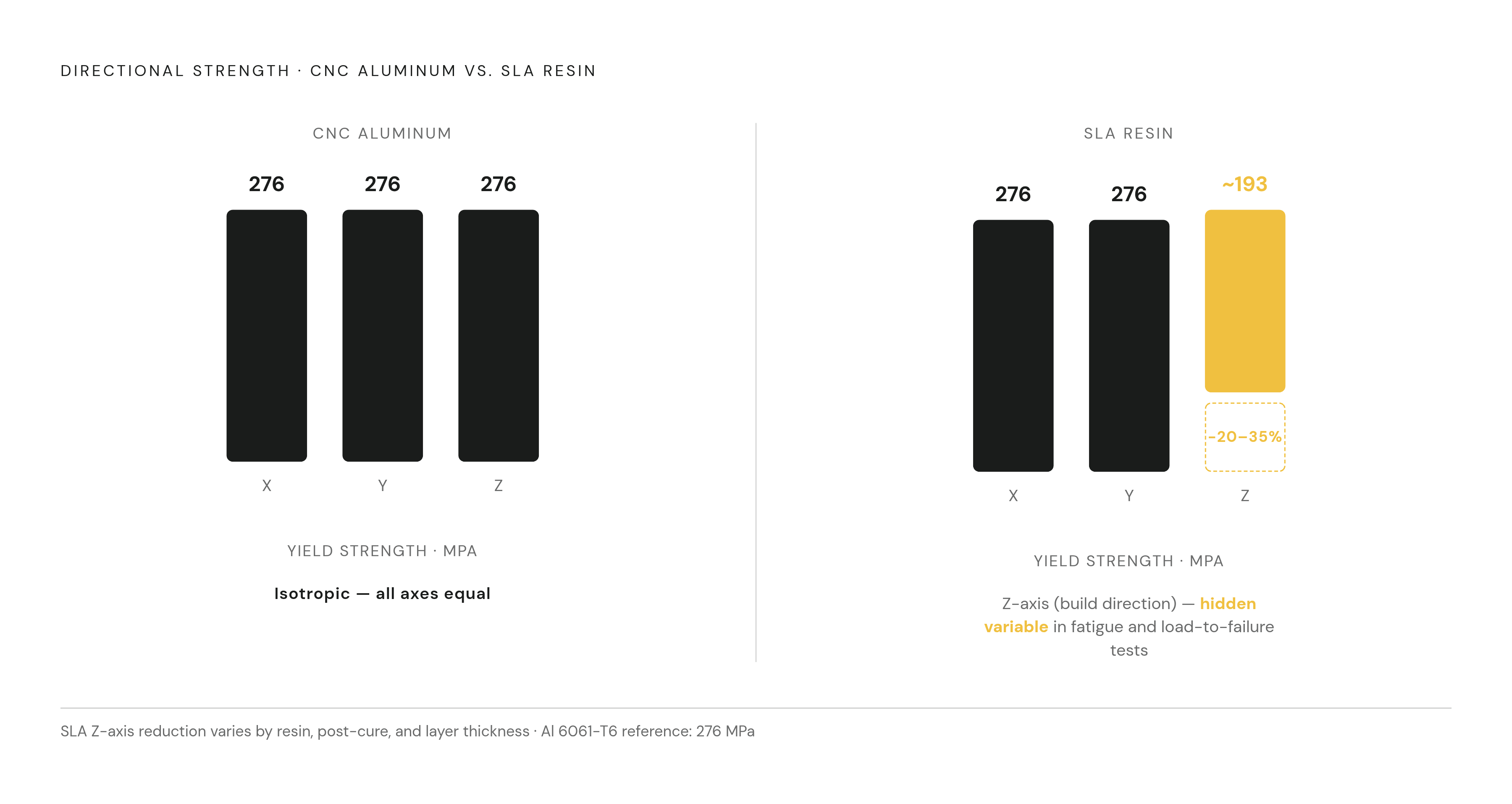
SLA fails as a substitute for aluminum the moment a test measures mechanical, thermal, or wear behavior rather than geometry. The layer-built structure introduces a 20% to 35% Z-axis strength penalty, and standard SLA resins run brittle under impact and cyclic loading, so fatigue life figures, pressure and leak results, and load-to-failure numbers off a printed part do not transfer to a machined aluminum version. Thermal tests hit the same wall: even the best heat-resistant resin formulations fall well short of aluminum's 167 W/m·K conductivity, making SLA useless for anything built around shedding heat or cycling through temperature swings. CNC is the right choice for any of those tests, because a part cut from certified 6061-T6 billet carries the same yield strength, the same thermal conductivity, and the same isotropic grain structure as the production part it is meant to represent.
Four things decide whether "aluminum-like" holds up or falls apart: strength isotropy, thermal behavior, achievable tolerance, and surface finish. Each cuts differently depending on which process made the part, and picking wrong on any one of them wastes the whole test.
How CNC machining preserves aluminum's certified material properties in the finished part
CNC starts with certified billet or bar stock and cuts material away. The finished part carries the same alloy designation and heat treat condition as the raw stock it came from. There's no layering, no cure step, no chemistry change between raw material and finished part.
That matters more than it sounds like it should. A prototype cut from 6061-T6 aluminum has the same yield strength (276 MPa) and the same thermal conductivity (167 W/m·K) as a production part machined from the same bar. Grain runs continuous through the part instead of stacking up in layers, so strength is isotropic: load it from any direction and it responds the same way. That's what makes CNC parts trustworthy for fatigue testing, pressure testing, thermal cycling, and wear testing, where the whole point is predicting how the production part holds up over time.
Complexity is where CNC hits a real wall, though. Internal channels, lattice structures, and undercuts need multi-axis setups, and 5-axis machining can run 300% to 600% more than a straightforward 3-axis job. Ask honestly, before committing, whether the geometry even suits cutting material away instead of building it up. The cost curve punishes complexity fast, and there's no way around it. If a part needs deep internal channels or lattice geometry, CNC usually isn't the right tool, no matter how much the team wants metal for testing.
What SLA actually produces, and where the "aluminum-like" claim holds or breaks
SLA covers a spread of resin families: standard visual resins, engineering-grade tough resins, durable PP-like resins, heat-resistant formulations, optical-clarity resins. Each one has its own ceiling, and lumping them under "aluminum-like" hides more than it reveals. That phrase should raise a flag every time it shows up on a quote. Most of the time it means the resin looks right in a render, not that it survives a real load.
Rigid 10K resin sits at the top of the SLA stiffness range. Rigid 10K resin sits at the top of the SLA stiffness range, but stiffness and toughness aren't the same trait, and a datasheet touting one tells you nothing about the other.
Standard SLA resins run brittle under impact and cyclic loading. That's the gap that matters most once a part has to survive a real functional test instead of just looking right in a photo. Stack the anisotropy problem on top of that: SLA parts build up in layers, and the interfaces between those layers are weaker than the bulk resin. Published figures put the Z-axis strength cut at 20% to 35% compared to the X-Y plane. Machined aluminum doesn't care which way it sat on the table; SLA absolutely does, because print orientation decides where the weak plane ends up relative to the load.
Heat-resistant resin formulations push the usable temperature range higher, but even the best of these fall well short of aluminum's 167 W/m·K conductivity. SLA can't stand in for aluminum in anything built around shedding heat or cycling through temperature swings. Don't spec it there, and don't let a vendor talk you into it.
Where SLA earns its keep: surface finish, fine detail, internal geometry that would be a nightmare to machine. If the test is about form, fit, ergonomics, or watching fluid move through a channel, SLA's strengths are exactly what the test needs.
Tolerance and surface finish: the numbers that decide whether a part fits and functions
CNC's baseline tolerance is ±0.005 inches, or about ±0.13 mm. SLA's best case reaches ±0.05 mm, but the published range stretches to ±0.2 mm depending on part size, resin choice, and post-processing. That's a wide band, and it sits on the loose end of most interface-critical work. Anyone quoting SLA at ±0.05 mm across the board is quoting the best day, not the average one. Treat that number with suspicion.
For clearance fits, locating features, and bearing bores, CNC's ±0.05 to ±0.13 mm range holds up across a full production run. SLA's spread means fit has to get checked part by part, since the tenth part off the printer won't necessarily match the first. For genuinely critical features like press-fit bores, CNC shops can hold ±0.0005 inches, a level no SLA resin system reaches.
Surface finish tells a similar story. Industrial 3D printing, including SLA, comes off the printer around Ra 3.2 to 6.3 μm, which works fine for plenty of functional uses. CNC does better straight off the machine, and secondary operations tighten that further.
Here's the piece that gets missed most often: if the prototype has to mate with a part that'll be machined in production, printing the prototype in resin adds a fit variable a machined prototype never would have. The test ends up measuring the resin's dimensional quirks as much as the design itself, and nobody notices until the numbers don't add up on the bench.
Tightening CNC tolerances isn't free either. Specifying ±0.002 inches instead of the standard baseline adds 25% to 50% to cost, and blanket tight-tolerance callouts across a whole part waste money on features that never needed it. Pick tolerances selectively: tight where the fit actually demands it, loose everywhere else.
Which test types expose SLA's limits and make CNC the right choice instead?
Some tests don't care which process made the part. Assembly fit checks, confirming clearances and envelope dimensions, land the same whether the part is aluminum or resin. Ergonomic reviews, hand feel, weight distribution, work fine too, though any material differences between resin and aluminum are their own variables worth tracking. Form and cosmetic review, surface quality, parting lines, feature placement, stay process-agnostic as well. Even basic snap-fit function holds up on tough or durable SLA resin, as long as the loads stay well under what the production part would actually see.
Other tests fall apart the moment resin stands in for metal, and this is where most bad calls get made. Fatigue testing is the clearest case: SLA's layer interfaces behave nothing like continuous aluminum grain, so fatigue life numbers off a printed part don't transfer to the machined version. Pressure and leak testing hits the same wall, since the layer-built structure of an SLA part behaves differently under pressure than a machined and sealed aluminum part. A resin part might pass or fail for reasons that have nothing to do with the design.
Thermal cycling breaks down for reasons already covered: aluminum's conductivity and expansion behavior are predictable, resin's aren't, and the two don't map onto each other. Wear and friction testing suffers because resin and metal respond to contact and abrasion in fundamentally different ways. Load-to-failure testing is the riskiest of all: with a 20% to 35% Z-axis penalty and a tendency toward brittle fracture, an SLA part fails differently than aluminum along the same load path, and it fails at the wrong number too.
The rule underneath all of this: once a test measures mechanical, thermal, or wear behavior rather than just geometry, the material has to match the production part. Ignore that and the test stops telling you about the design; the results end up describing the prototype's own quirks instead. That distinction carries real weight, and it's the whole reason the test exists.
DFM decisions that change depending on which process you commit to
CNC has its own list of cost drivers, and they show up whether or not a designer plans for them. Internal corners need at least a 0.030 inch radius for standard tooling; anything sharper needs EDM or a specialized setup. Wall thickness below 0.8 mm risks chatter and deflection during the cut, and 1.5 mm is the realistic floor for reliable results. Complex curves and varying radii can triple programming time and quadruple machining cost next to geometry that stays simple and axis-aligned. Stack a few of these onto one part and the compounding effect gets ugly fast: DFM choices made at the concept stage can swing lead times anywhere from 25% to 1,480%, and cost from 15% to 800%.
There's a design-transfer trap worth flagging too. Parts headed eventually to die casting or injection molding need a CNC-specific version of the design, because draft angles and filleted features that work fine in casting make CNC machining harder, not easier.
SLA's DFM traps are quieter, because they don't surface until the part is under load and fails. Build orientation is the single biggest decision in the whole process; it decides whether the weakest plane lines up with the highest-stress direction, and getting that wrong never shows up on an inspection report. SLA's real advantage over CNC, geometry a cutting tool can't reach, internal channels, undercuts, organic shapes, only pays off if the resin can actually carry the loads the application needs. Specify SLA for a structural role and its real strength, fast turnaround and complex geometry at low cost for non-structural parts, goes to waste.
The practical fallout: an engineer who designs around SLA's geometric freedom and then has to switch to CNC usually ends up redesigning the part from scratch, since deep internal features and thin walls that make sense in resin are exactly what drives CNC cost through the roof.
The hybrid approach: using both processes on the same prototype program
More prototype programs now split the bill of materials between the two processes instead of picking one for the whole assembly, and that's the right call more often than not. Structural, load-bearing, or thermally active components get machined aluminum, while housings, brackets, covers, and other parts where geometry and appearance matter more than mechanical equivalence go to SLA.
The decision runs component by component: for each part, ask what test it has to survive and what that test demands of the material, then assign the process to the requirement, not to a budget line. A typical split looks like this: machined aluminum for anything seeing load, thermal cycling, or wear during testing; rigid or tough SLA resin for housings and ergonomic elements checked on fit and form alone; durable or flexible SLA resin for snap fits, gaskets, and other flexible parts tested at low load for assembly function.
This exposes a real logistics problem, though. Splitting a BOM across two processes usually means two vendors, unless one shop runs both, and coordinating separate suppliers for a single prototype assembly adds lead time and gives errors more room to creep in. A sourcing partner that quotes CNC and SLA together, on one purchase order, cuts that coordination overhead out and gets machined and printed parts arriving together, ready to assemble instead of waiting on each other. OneWeekParts, a single-source custom parts and assembly supplier that handles CNC machining and 3D printing alongside sheet metal, casting, and other processes under one quote, is one option built specifically for that kind of mixed-process BOM.
Reading a part drawing to make the process call before sending files
Start with the governing test: what is this prototype actually built to prove out? If the answer touches load, heat, pressure, wear, or fatigue, the part needs material equivalence to production. That points toward CNC, regardless of what the timeline pressure says.
Next, check the tolerance callouts. Anything tighter than ±0.05 mm rules out SLA without secondary machining, while critical features at ±0.13 mm or looser make SLA's range workable.
Then walk the geometry feature by feature. Internal corners tighter than a 0.030 inch radius push toward EDM or a redesign on the CNC side. Walls under 1.5 mm are often fine for SLA but risky for CNC below 0.8 mm. Internal channels or fully enclosed voids favor SLA outright, since CNC needs split bodies or multiple setups to reach the same geometry.
After that, check the load path. If the part carries structural load, find the critical axis, and if SLA is on the table, confirm the print's strongest plane, the X-Y direction, lines up with that axis. Factor in the 20% to 35% strength cut running through the Z-axis and plan around it if it doesn't.
Last, make the call per component, not per project. A single prototype program can correctly run CNC on three parts and SLA on five others in the same assembly, and that's a legitimate outcome on its own merits, not a compromise. The goal is matching each part to the test it needs to pass, not keeping the whole BOM on one process for the sake of tidiness. Raise any doubt about tolerances, wall thickness, or feature geometry at the quoting stage, before the design gets locked and the first parts are already cut or printed.