Aluminum Die Casting vs. CNC Machined Aluminum for Structural Housings
Die casting wins at high volume, but machining often costs less until you're ready to commit.
Choosing between aluminum die casting and CNC machining for a structural housing comes down to four things: how many units you need, how tight the tolerances are, how complex the geometry is, and where you sit in the development timeline. Most teams get this wrong in the same way: they pick a process once, early, and assume it holds for the whole program. It doesn't. The process that wins at the prototype stage is often the wrong one at volume, and the reverse is just as true. That's the mistake worth naming up front, because it's the one that shows up again and again once a die is already cut and the budget for changing course is gone.
Structural housings ask for a lot at once: dimensional precision, mechanical strength, decent surface quality, low cost, and a schedule that doesn't blow the program. Both processes show up in production structural housings across a wide range of industries. Matching process physics to what the part actually needs, at the volume you actually need it, is the whole job. Get that match wrong and no amount of downstream inspection fixes it.
What each process actually does to aluminum and why that difference in physics matters for housings
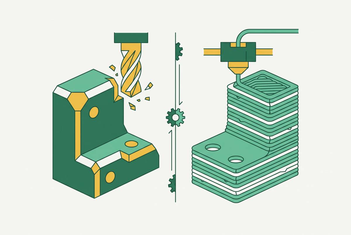
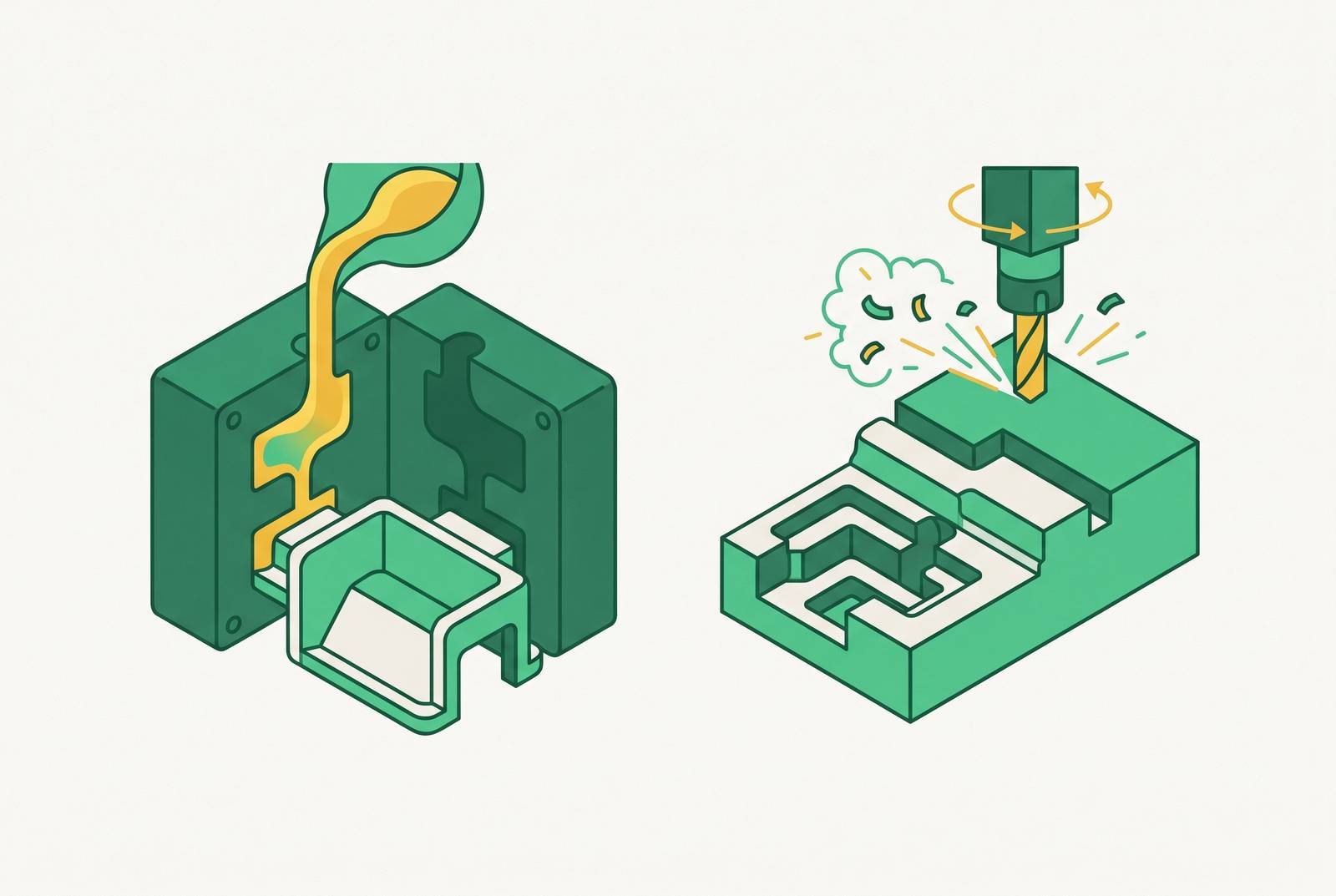
CNC machining cuts material away from a solid block. A computer-controlled tool removes stock from a billet of wrought aluminum until the final shape shows up. The aluminum's grain structure never changes; it stays intact and oriented the way it was when the billet got rolled or extruded.
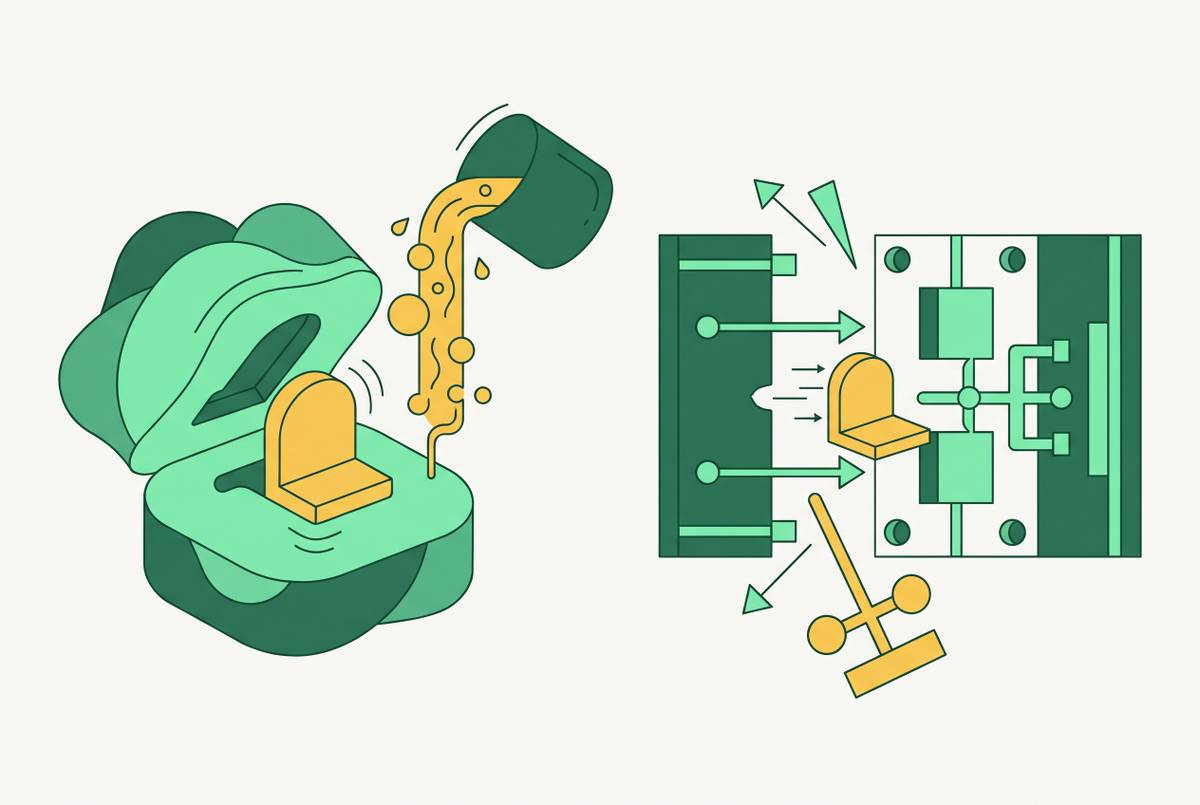
Die casting works the opposite way. Molten aluminum gets shot into a hardened steel die under real pressure, somewhere between 1,500 and over 25,000 PSI depending on the setup, and it solidifies into a near-final shape inside that die. The grain structure that comes out is cast, and that distinction matters more than it sounds like it should.
Machined parts from wrought alloys like 6061, 7075, or 2024 carry higher tensile strength, higher yield strength, and better fatigue resistance than cast parts. For a housing under cyclic load or the occasional impact, that gap shows up directly in how long the part lasts before something cracks. Die casting alloys such as A380 or A383 (also called ADC12) get formulated for fluidity, so the metal fills the die cleanly, not for peak mechanical performance. They're excellent for pumping out complex shapes at volume. They are the wrong choice when a part needs to survive the worst stress event of its life, and treating a die cast bracket like it has the same fatigue margin as a machined one is how parts fail early in the field. That risk is not marginal. It's the single most common design error on this list.
Die casting also carries a porosity risk that solid-billet machining just doesn't have. Gas pockets and shrinkage voids form inside a casting, and depending on where they land, they can undercut a housing's fatigue life or ruin a pressure seal. That's a real design and inspection burden, not a footnote, and it never shows up on the outside of the part.
Surface finish tells a similar story. CNC machining typically lands at Ra 1.6 to 3.2 μm straight off the tool, and tightening the cutting parameters can get that down to Ra 0.8 μm. As-cast surfaces run rougher and less consistent, and sealing faces or mating surfaces on a die cast part usually need a secondary operation to clean them up. One more detail worth knowing: aluminum die casting always runs cold-chamber, not hot-chamber, and that choice shapes cycle time and per-part cost downstream.
Tolerance and precision: what each process can hold and where the gap actually falls in practice
CNC machining routinely holds ±0.01 mm, and tighter setups push past that. That's the process to reach for on sealing surfaces, bearing bores, press fits, and threaded bosses, anywhere two parts need to mate without slop.
Die casting, as-cast, lands closer to ±0.1 mm on small features, and the number gets looser as the part grows or the geometry gets more involved. Ten times looser is a substantial difference, not a rounding one. It's the gap between a part that needs no further touch and one that needs a second operation before it can do its job.
Most shops solve this with a hybrid: cast the part to near-net shape, then CNC finish the handful of surfaces that actually need precision. Done right, that gets critical features down to around ±0.05 mm while the rest of the part keeps the geometry efficiency casting gives for free. A housing with a few precision bores or mating faces surrounded by non-critical geometry is almost always a candidate for this approach, and that cost belongs in the plan from day one, not something discovered after first article samples come back.
Alloy choice matters here too, and it's easy to overlook. A die casting alloy picked for how well it fills a mold behaves differently under a milling cutter than a wrought alloy picked for machinability. Tolerance requirements should drive the process decision and the material decision together, not as two separate conversations happening at different desks.
Geometry complexity and what each process can and cannot form
Die casting wins on thin walls, integrated ribs, bosses, and features cast directly into the part: snap fits, heat sink fins, thread starts. Machining those same features from a solid block would be slow, expensive, or in some cases just not possible.
CNC machining wins on complex external contours, especially with a 5-axis setup, and on internal channels or cavities a die simply can't produce. Anything that needs zero draft, or any geometry that would trap gas or fight the mold during ejection, belongs in the machining column.
Die casting comes with its own rulebook, and ignoring it is how programs end up re-cutting a die mid-development:
- Draft angles of roughly 1 to 5 degrees are required on vertical walls so the part can eject cleanly, which shapes how the housing's sidewalls and internal features get drawn.
- Wall thickness needs to stay uniform. Uneven thickness invites shrinkage porosity and cold shuts, and any thin-to-thick transition needs careful handling.
- Undercuts need slides or lifters built into the tool, and every one of those adds real cost to the mold.
- Sharp internal corners are a problem twice over: a stress concentration in the finished part, and a flow obstruction while the metal's still filling the die. Fillets and radii are non-negotiable at transitions.
CNC machining has its own limits, just different ones. Deep, narrow pockets slow the process down and risk tool deflection. Fully enclosed internal geometry often forces multiple setups or a trip to EDM. Thin walls on a tall feature chatter under the cutter.
A housing designed around CNC habits and handed to a die caster will need a redesign, and the reverse holds just as true. 5-axis CNC opens up compound-curve geometry, common in lighting housings and automotive brackets, that a 3-axis setup can't reach in one pass. Most of a part's cost, lead time, and quality risk gets locked in during the design phase, well before anyone picks a manufacturing process. Making the geometry call after the process call is backwards, one of the most common ways these programs run over.
Volume economics and tooling investment: where the crossover point actually sits
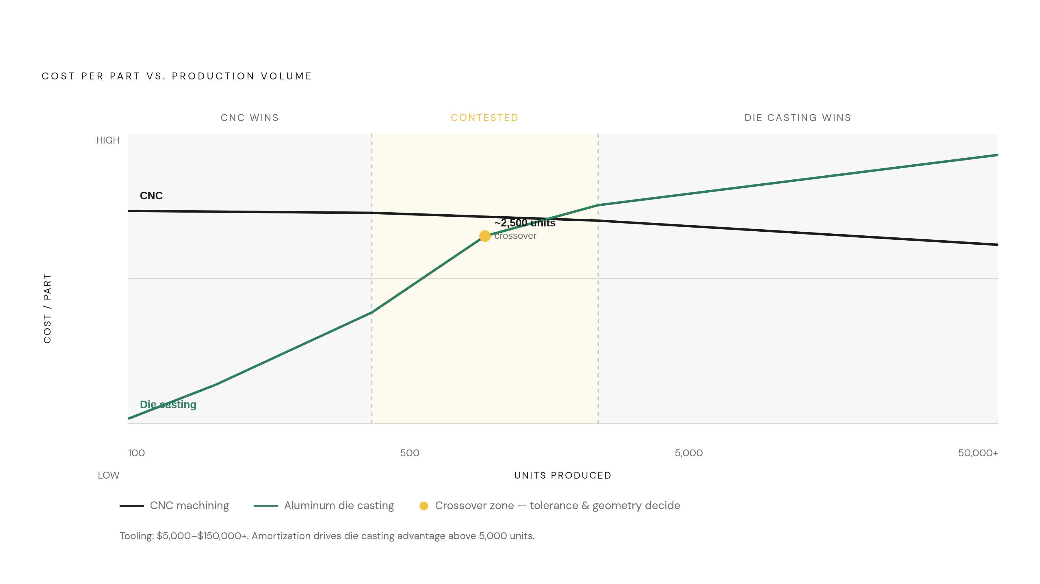
CNC machining carries no tooling cost. Part one and part ten cost roughly the same to make, which makes it the natural fit for low-volume runs and prototypes.
Die casting flips that structure: a large upfront hit on the die, then a steep drop in per-part cost as volume climbs. Tooling for a typical part runs somewhere between $5,000 and $150,000 or more, and complex or oversized parts push past that range. Every undercut that needs a slide or lifter adds to the number.
Once the tooling cost is known, the math is simple: spread a $20,000 die over a small run and it adds real cost to every part; spread it over a large run and that cost per part shrinks toward nothing. The break-even volume is just tooling cost divided by the per-part savings versus machining. CNC wins under roughly 500 parts, full stop. Die casting starts winning economically somewhere north of 5,000. The territory between those two numbers is where tolerance, geometry, and schedule matter more than raw unit cost, and volume alone won't settle the argument there.
Production dies are built to survive a long run, often rated for 100,000 cycles or more under good process control. Soft aluminum tooling costs a lot less and works fine for smaller validation runs, but it won't hold up under hardened production volumes, and trying to stretch it there is how tools crack mid-run. Die casting quotes can also carry layered markups depending on how the supply chain is structured, so it's worth pulling apart what actually goes into the number before signing off on a proposal. Automotive programs add another layer entirely: multi-year contracts and PPAP qualification cycles represent a tooling commitment well beyond what a typical mechanical housing program signs up for, worth weighing separately if the program timeline is short.
Lead time across the development cycle: what each process costs you in calendar weeks
CNC machining turns around fast. Straightforward jobs typically ship first parts in one to two days if material is available, and because there's no tooling in the loop, a design change costs some CAM reprogramming time, not a mold rebuild.
Production die casting runs on a different clock. Cutting the tool and getting first production samples typically takes three to six weeks, and regulated industries stack first-article and PPAP cycles on top of that.
Rapid or soft tooling splits the difference. Aluminum or soft steel molds, suited to limited validation quantities, skip the hardened production die, and some suppliers get production-representative samples back in around 30 days. That middle option matters more than it gets credit for, being the option most teams skip when they shouldn't.
For a housing sitting on the critical path of an assembly, blocking mechanical or electrical integration downstream, tooling lead time sits at the center of the schedule. It's one of the biggest cost drivers in the whole program. If the housing shares a BOM with composites, custom gaskets, or other fabricated parts, the longest lead process in that mix sets the assembly date for everything else, so the housing decision has to account for what else is waiting on it.
Design changes made after the die is cut cost real money and real weeks. The earlier the design goes through DFM with the casting supplier, the cheaper those changes stay. A change at the concept stage costs nothing. The same change after the mold is cut runs into serious money and pushes the whole schedule sideways.
Where prototyping fits and why CNC prototypes don't fully de-risk a die cast housing design
Three routes exist for prototyping a structural housing, and they answer different questions.
A CNC prototype is the fastest way to check fit, envelope, and mounting. What it won't show: how the part behaves as a casting, how much it shrinks, or what the as-cast surface actually looks like. Rapid or soft tooling sits in the middle, giving some casting-specific validation at low volume without the cost of a full production die. A production-process prototype, meaning an actual die cast part, is the most representative option, and also the most expensive and slowest to get.
A housing that sails through CNC prototype validation can still run into die casting problems later: wall thickness issues, fill problems, ejection conflicts, none of which show up until the part gets cast for real. Machined parts from wrought alloy carry a different grain structure, different porosity behavior, and different surface finish than a cast part, so passing one test doesn't mean the other test is passed too. That's the trap: teams greenlight tooling off a CNC prototype and then find out at first-shot inspection that the wall the designer thinned out for weight won't fill. Trusting a CNC prototype to validate a die cast design is the single biggest false confidence in this whole process, and it's an avoidable one.
Investment casting is worth knowing about as an alternative process, and it shows up in aerospace and medical work where it suits small- to medium-complexity parts. Soft aluminum tooling serves a similar purpose: it costs a fraction of a hardened production die and works well for validation quantities before anyone commits to full tooling.
When the RFQ goes out for prototyping, the package should include separate CAD models for the as-cast and machined states (not one file trying to do both), 2D drawings with tolerances called out, material and process specs, quantities, inspection requirements, and clear notes on which features are actually critical. Handing a casting supplier only the machined model is one of the more common, and most avoidable, sources of rework later.
The hybrid approach: die casting the body and machining the critical surfaces
The hybrid workflow looks like this: cast the part to near-net shape for geometry efficiency, shot blast or tumble it for a uniform surface, run leak or pressure tests on functional housings, then CNC machine the critical surfaces, bores, threads, sealing faces, and mating datums.
Done this way, the hybrid approach reaches around ±0.05 mm on the machined features, while the cast body still holds geometry that would be slow or impossible to produce from a solid billet. This is a design choice built in from the start. It's the intended production model for a lot of structural housings, especially in automotive, robotics, and industrial automation, where complex external shapes have to coexist with tight interface tolerances.
Timing is the catch. The features that will get machined later need to be identified before the die itself gets designed, so the die leaves enough extra stock in those spots. A die designed without that information won't leave enough material, and the machining step either fails or has to work around a shortfall. Wire EDM can enter the picture for fine features that milling can't reach inside the die itself.
Inspection has to happen twice: a CMM check on the cast geometry first, then a second pass after the critical surfaces get machined. Skipping either step on a housing headed into structural service is asking for trouble. And because the casting and the secondary machining are really one continuous process, splitting them across two separate vendors introduces tolerance stack-up and schedule risk right at the handoff. A single partner who can run both steps removes that risk entirely, and that's worth more than whatever small savings come from shopping the two operations out separately.
Quality assurance requirements specific to structural aluminum housings
Die cast structural housings carry defect risks that a machined part from solid billet simply doesn't have: gas porosity, shrinkage porosity, cold shuts, inclusions. None of these show up on the surface. All of them can undercut structural integrity if they land in the wrong spot, and none of them get caught by eyeballing the part.
Real-time X-ray inspection catches internal gas pockets, shrinkage porosity, and micro-cracks, and results typically get graded against a standard like ASTM E505, which scores discontinuities on a 1-to-4 scale. Ultrasonic scanning adds a second layer of confirmation on top of that.
CMM inspection checks the finished geometry against the original CAD model and is the standard for first-article inspection confirm whether both the cast and the machined features actually fall within spec.
On certification, ISO 9001 sets the baseline for documented process control. IATF 16949 goes further, adding automotive-grade risk analysis and full material traceability for programs that need it.
Pressure and leak testing matters for any functional housing, fluid, pneumatic, or electronics enclosure, and its place in the inspection sequence should be planned explicitly, so a leak traces back to the casting itself rather than a machined interface added later.
Process control during the casting run, tracking melt temperature, die pressure, and cooling rate shot to shot, is what separates a supplier with a low reject rate from one that scraps a chunk of every batch. Ask a supplier directly how those parameters get logged and what happens when one drifts out of range. And on inspection cadence: checking every part before shipment catches intermittent defects that sampling-based inspection misses entirely. That gap matters more in die casting than in machining, because casting defects don't show up consistently batch to batch, sampling can pass a batch that's hiding a bad shot right in the middle of it.
A practical decision framework: mapping volume, tolerance, geometry,
Run the four questions in order, because the answer to each one narrows the field for the next.
Volume first. Under roughly 500 units, CNC machining wins on cost almost every time, tooling investment just doesn't pay off at that quantity. Above roughly 5,000 units, die casting's per-part economics take over. Between those two numbers, volume alone won't settle it, and the next three questions decide.
Tolerance second. A housing with a handful of tight features surrounded by moderate geometry is a hybrid candidate: cast the body, machine the critical surfaces. A housing with uniform, moderate tolerances across the whole part is a better fit for as-cast production with no secondary work at all.
Geometry third. Thin walls, integrated bosses, and complex external shapes favor die casting. Deep pockets, non-drafted features, and enclosed internal channels favor machining. A part that leans heavily on both may need the hybrid approach regardless of what volume says.
Cycle stage last. Early concept work almost always favors CNC prototypes for speed, but a design headed for die casting at volume needs a production-process prototype, or at minimum soft tooling, before anyone signs off on the final die. Skipping that step to save a few weeks is how programs end up re-cutting a tool after the first production run reveals a fill problem nobody caught.
None of these four questions gets answered alone. Volume sets the economic frame, tolerance and geometry set the technical limits inside that frame, and cycle stage decides how much risk is worth carrying into the next phase. Treating the process choice as a single decision made once, instead of one that gets revisited at each stage, is the single most common reason housings end up over budget or behind schedule.
Sources
- Detailed Comparison: CNC Machined Aluminum vs. Die Cast Aluminum
- CNC Machining vs. Die Casting: The Complete Decision Guide [2026]
- Die Casting vs CNC Machining for Aluminum Parts
- Aluminum Die Casting vs CNC: Pros, Cons & Cost Guide
- Cast vs Machined Aluminum: 5 Considerations and 4 Recommendations - JTR
- Die Casting DFM: Streamlined design and manufacturing practices
- Beginner's Guide to Die Cast Design | Dynacast
- mecomeco.com