CNC Machining vs. FDM for Structural Bracket Geometries
CNC machining delivers isotropic strength; FDM prints weak along the Z-axis.
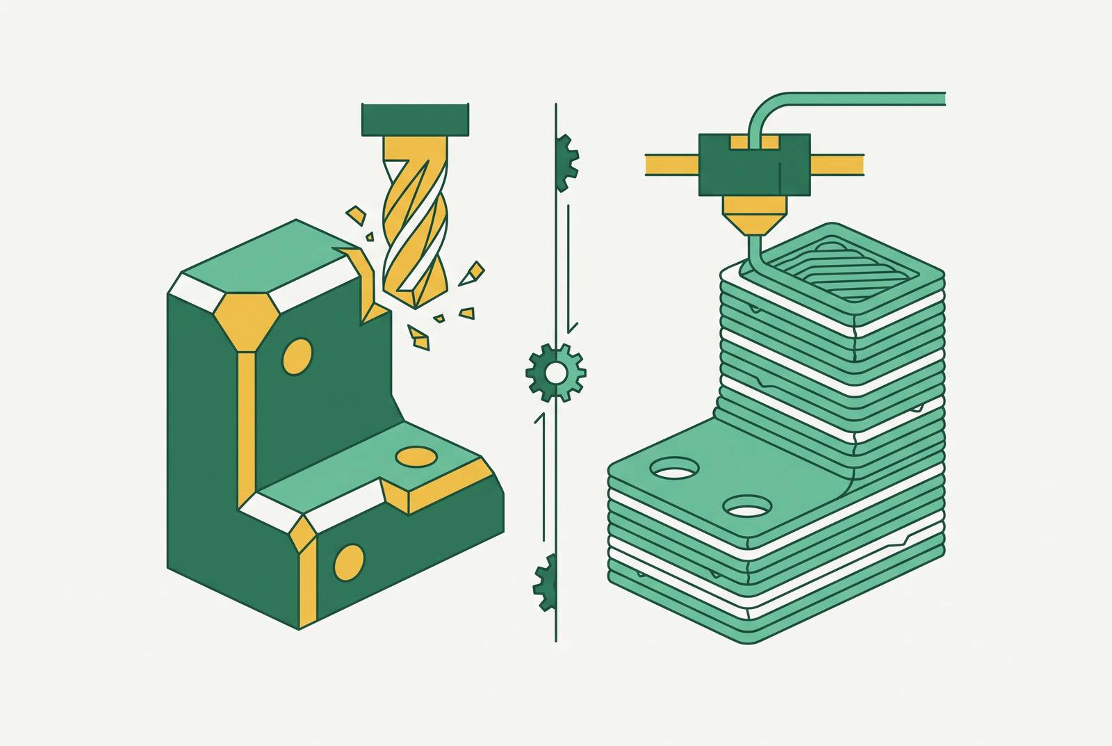
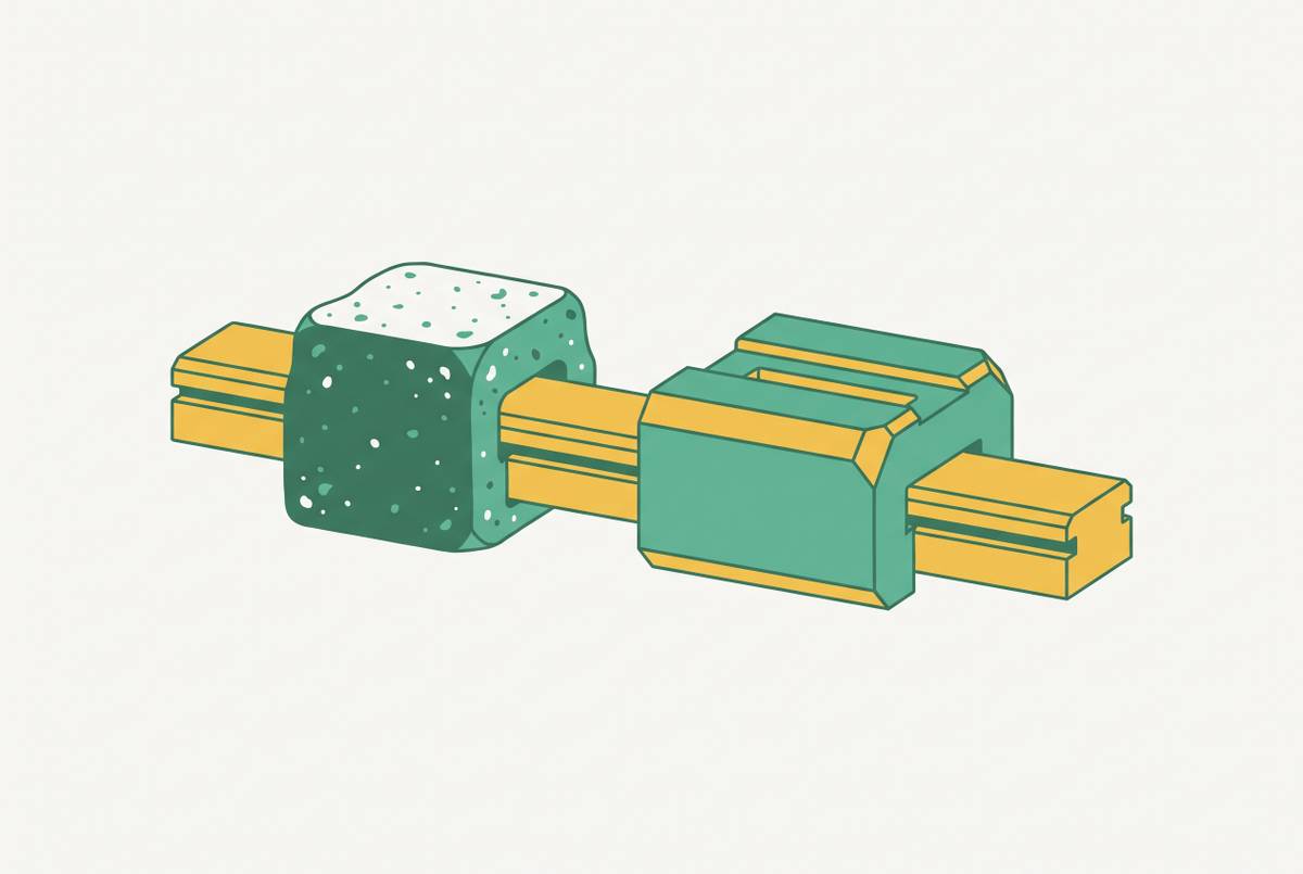
Structural brackets carry load by definition, and the process that makes them decides how that load moves through the part. CNC machining and FDM printing produce brackets with genuinely different mechanical behavior, and different price tags too. The split comes down to grain: CNC cuts a bracket from solid stock and keeps that stock's internal structure intact, while FDM builds a bracket layer by layer, and the bond between those layers becomes the weak link. That's the gap between an isotropic part, one with the same strength in every direction, and an anisotropic part, one that's strong one way and soft another. Anyone treating FDM and CNC as interchangeable for a load-bearing bracket is setting that part up to fail somewhere nobody thought to test, and that mistake is more common than it should be.
FDM parts typically show only 50 to 70% of their XY-direction strength when loaded along the Z-axis. That gap is mechanical in origin: it comes down to how well one layer bonds to the next, and that interlayer weld is never as strong as the surrounding plastic. CNC-machined parts, by contrast, cut from solid stock that keeps its internal grain intact, typically run 40 to 60% higher in tensile strength than FDM parts made from a nominally identical material. Printing a bracket upright puts its weakest axis, the layer-to-layer bond, directly in the path of the load that matters most, and no infill setting compensates for a part that is simply oriented wrong.
How much weaker are FDM parts along Z versus XY, and where does that weakness come from?
Start with the number that should change how anyone reads an FDM datasheet: parts printed on an FDM machine typically show only 50 to 70% of their XY-direction strength when loaded along the Z-axis. The cause is mechanical, not mysterious. It comes down to how well one layer welds to the next, and that weld is never as strong as the plastic around it. CNC-machined parts typically run 40 to 60% higher in tensile strength than FDM parts made from a nominally identical material, and that gap separates a part that behaves the way its datasheet promises from one that doesn't come close.
Material choice matters more than infill tuning, and orientation is the variable most engineers get wrong. A peer-reviewed study found PPA carbon-fiber filament, printed flat with a cross infill pattern, hit 75.8 MPa tensile and 102.3 MPa flexural strength. ABS, printed upright with a grid pattern in the same study, managed only 37.8 MPa tensile and 49.5 MPa flexural. Same broad material family, wildly different outcome. Printing a part upright puts its weakest axis, the layer-to-layer bond, right in the path of the load that matters most, and no infill setting fixes a part that's just oriented wrong.
FDM can still be strong, but only when strength gets designed in on purpose, part by part, rather than assumed off a spec sheet the way you'd assume it from a block of aluminum. A bracket with one fixed, well-understood load direction is a solid FDM candidate. One that sees load from shifting or multiple directions isn't, and no filament upgrade changes that.
What bracket geometry does to each process's strengths and limits
CNC geometry lives and dies by tool physics. Every internal corner needs a radius no smaller than the end mill cutting it, so a sharp 90-degree internal corner just isn't possible without EDM or broaching bolted onto the job. Deep pockets bring tool deflection into play, which slows feed rates and sometimes forces a second operation just to clean up a wall. Every flip for a new setup stacks cost and positional error on top of the last one. Five-axis work, the kind needed for compound angles, can run 300 to 600% more than a standard three-axis job, so that complexity better be earning its keep structurally, not just looking good in a render.
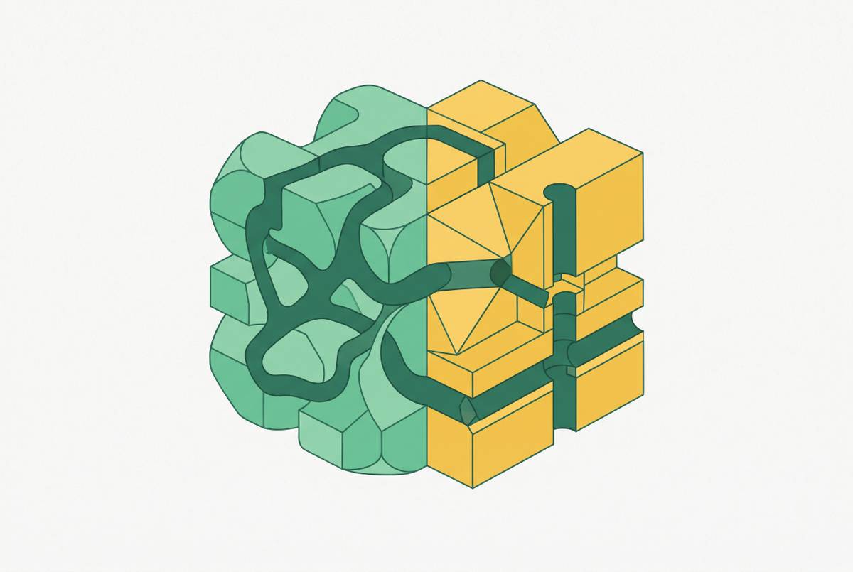
FDM's constraints run the opposite direction. Overhangs, lattice structures, internal channels, organic swept shapes, the stuff that would eat three CNC setups and a fixture redesign prints in a single run. Topology-optimized brackets, the ones that carve material out of anywhere the load isn't going, are FDM's strongest structural argument. There's a catch, though: overhangs steeper than 45 degrees still need support material, and support means labor to remove plus a rougher surface everywhere it touched.
Run that logic against real bracket types and the split gets obvious fast. A simple lug bracket, a mounting flange, a clevis bracket: straightforward geometry, direct load path, CNC wins without much of an argument. A bracket with internal cavities for weight savings, or a cable channel routed through the body, prints in one FDM pass; CNC needs multiple setups or an EDM operation to get there. A bracket with a critical bearing bore or mounting hole is a CNC job, full stop. CNC holds ±0.13 mm on non-critical features as a baseline; FDM typically holds ±0.5 mm, and that's often too loose for a slip fit or a fastener that has to line up with something else.
The geometry that looks great in a topology-optimization render can quietly wreck the one feature the whole assembly hangs on: a bore that needs to be round, a face that needs to sit flat against another part.
Tolerance and surface finish requirements that force the decision
Tolerance works as a gate here, not a style preference. CNC's non-critical baseline sits at ±0.13 mm, while FDM's baseline runs about four times looser, at ±0.5 mm. Metal AM processes like DMLS get closer to ±0.1 mm, though critical features may still require additional process steps that reduce the advantage over CNC.
On a bracket, the tolerance gap shows up in three places. Bearing bores and bushing seats need a slip or press fit that FDM can't deliver without a secondary machining pass. Mating flanges bolted to a precision assembly compound their error fast: four holes at ±0.5 mm each, and the stack-up eats your margin before the bolts are even torqued. Tapped holes in printed plastic often can't hold clamping load at all without a heat-set insert pressed in afterward.
Surface finish carries its own structural cost, and this is where FDM gets underrated as a risk. Layer lines act as stress concentrators, not just cosmetic marks. Under cyclic loading, cracks start at those surface ridges long before the bulk material would fail on its own. Research published in the Journal of Composites Science found that CNC-milling the edges of FDM parts improved elongation at break by 13.45% to 33.55%, depending on filament diameter, just by cleaning up the surface where cracks like to start. That's the real case for hybrid workflows: print the geometry, machine the surfaces that see fatigue.
The rule holds regardless of which process looks cheaper up front. Any feature on the bracket with a fit or function requirement gets checked against both tolerance baselines before the design locks. Finding the mismatch after first article inspection costs far more, in tooling and in schedule, than checking it on paper would have.
Material options that are only available through one process or the other
CNC opens up the full metal catalog, and that's not a small advantage. Aluminum 6061-T6 is a common choice for prototype and general-purpose structural brackets, widely used for its machinability and availability. Aluminum 7075-T6 steps up to 73 ksi (503 MPa) yield strength at 2.81 g/cm³, for jobs where weight and strength both matter at once. Titanium Ti-6Al-4V goes further still: 120 ksi (827 MPa) yield and 160 ksi (1,103 MPa) tensile at 4.43 g/cm³, the best strength-to-weight ratio on the table. It runs $25 to $50 a pound in bar stock and machines slowly, so it only earns its place when the mass budget genuinely demands it. Stainless steel grades serve brackets in wet or chemically hostile environments where corrosion resistance is the primary driver.
FDM's material menu tells a thinner story, and pretending otherwise sets up bad decisions down the line. Standard filaments, PLA, ABS, PETG, work fine for low-load, room-temperature parts, but their structural case falls apart under real demand. Engineering-grade materials, PEEK, Ultem, PPA reinforced with carbon fiber, close a lot of that gap, though the printer hardware and process control needed to run them reliably get expensive fast. SLS nylon deserves a mention here too: it reaches 90 to 100% of bulk material strength and behaves close enough to isotropic for plenty of structural jobs, but it's a separate process from FDM and shouldn't get lumped into this comparison.
Here's a pairing engineers miss constantly: a bracket that's plenty strong printed in PPA carbon-fiber might still need to be CNC aluminum if the service environment, heat, UV, chemical exposure, degrades the polymer over its service life. Printing strong enough for day one doesn't guarantee staying strong for year three. There are also jobs neither process handles well alone. Carbon fiber brackets offer a distinct manufacturing capability from either CNC or FDM, with strength-to-weight characteristics that differ meaningfully from aluminum. That's a distinct manufacturing capability from either CNC or FDM, worth knowing about before assuming one shop covers everything.
When FDM is the right call for a structural bracket, and what conditions must hold
FDM earns the job for a structural bracket when a handful of conditions line up at once, not just one of them. The load has to be well-understood and mostly uniaxial, with the part oriented so the main load axis runs along XY, never Z. The bracket should be sitting in a prototype or validation stage, where the goal is understanding how load moves through the design, not shipping a final part. The geometry should genuinely need FDM's freedom, lattices, internal channels, organic shapes, rather than complexity added for its own sake. Volume should sit in the 1 to 5 unit range, where paying $50 to $80 for an FDM part instead of $250 to $500 for a first CNC part actually moves a program's budget.
Load type is the sharpest filter available, and it's the one most people skip past. Static load in a known direction, with the part printed to put that load along XY: that's a defensible FDM structural choice. Dynamic, cyclic, or impact load turns FDM risky fast, because anisotropy and layer-line stress concentration compound under repeated cycles. CNC metal is the safer call there, full stop. Multi-axis or unpredictable loading takes isotropic material off the table as optional; FDM is out unless the design carries so much extra margin it stops looking efficient at all.
Engineering-grade filaments shift that line but don't erase it. PEEK or continuous-fiber FDM can take on more structural demand, but only if orientation discipline, process control, and inspection all rise to match. There's a failure-mode question underneath all of it too. The failure modes of CNC metal and FDM parts differ by nature of their material structure, and understanding how a part is likely to fail matters as much as knowing its nominal strength. Anywhere failure needs to be visible before it's catastrophic, safety hardware, anything with a person attached to it, that difference alone settles the argument for CNC.
Cost and lead time across the bracket development cycle
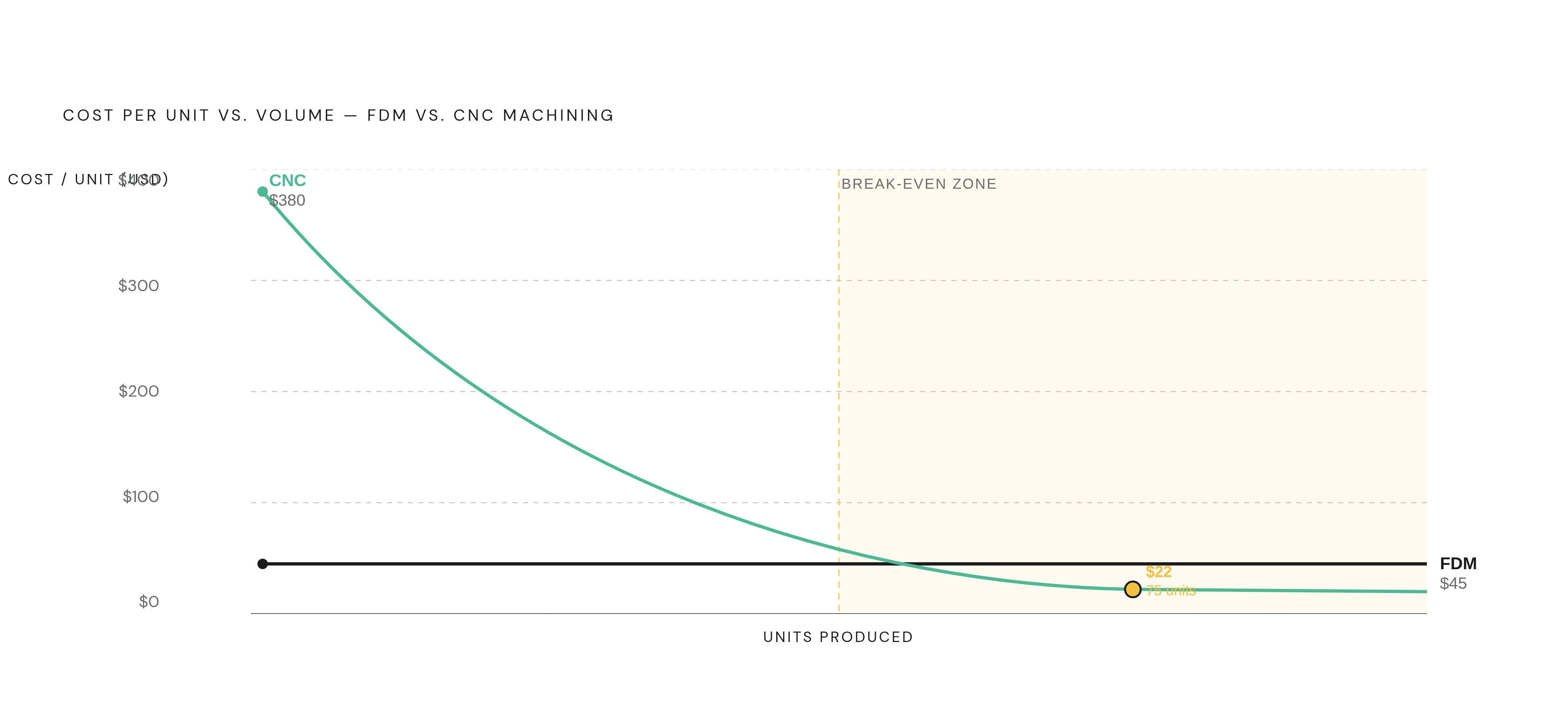
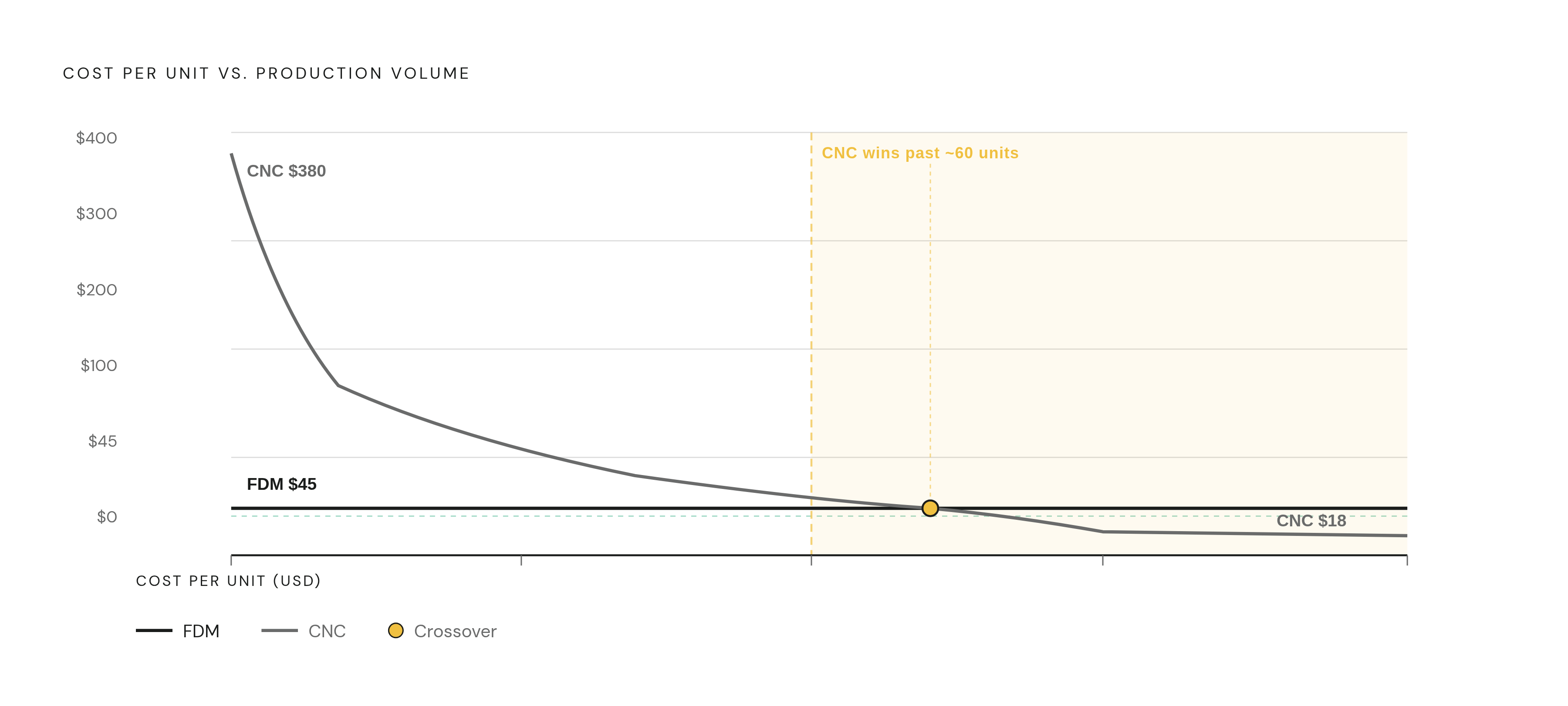
At low volumes, the cost gap is wide, and it favors FDM more than most people expect. A first CNC bracket typically runs $250 to $500 for a simple design, with that cost coming almost entirely from programming, fixturing, and setup, not material. The same bracket printed in FDM lands around $50 to $80. One documented example makes the crossover concrete: one documented bracket cost $45 to produce via FDM 3D printing and $380 for the first CNC unit; by the 75th unit, CNC cost had dropped to $22 while FDM held flat at $45. Break-even for most bracket geometries falls somewhere between 50 and 100 units. Past that point, sticking with FDM is just leaving money on the table.
That crossover shapes the whole development cycle. Early concept work and form/fit checks are where FDM makes financial sense, even when CNC aluminum is the eventual production plan. Functional validation, the stage where the part actually gets load-tested, calls for spending the $380 on CNC if the load is structural, because a failed load test on a plastic proxy costs more in wasted schedule than the machining setup did. Past 50 to 100 units, CNC's per-unit economics pull ahead by a wide margin, and no amount of print-farm scheduling changes that math.
Lead time tells a more nuanced story than most engineers expect. FDM and SLS typically deliver in 3 to 5 working days including post-processing. CNC through a high-volume job shop can run 10 or more working days once programming, tooling, and queue time stack up. Fast-turn CNC platforms close that gap, delivering standard jobs in 3 to 5 days with expedited options as fast as a single day. Standard production CNC runs still land around 7 to 10 days, with faster options available at the quoting stage.
None of this counts the cost that never shows up on a quote. DFM decisions made during the concept phase can drive manufacturing costs up anywhere from 15% to 800%, and lead times up 25% to nearly 1,500%, depending on how far off-base the design was. Getting DFM feedback before a bracket design locks, regardless of which process ends up making it, isn't optional on any program with a real schedule.
DFM decisions that determine whether a bracket design is manufacturable at all
For CNC brackets, a few rules decide whether the part gets made cleanly or turns into a change order. Internal corner radii need a minimum of 0.030 inches (0.76 mm); go sharper than that and the part either can't be cut with standard tooling or needs EDM added to the process, which adds cost and time neither side planned for. Five-axis features deserve the same scrutiny: if a compound-angle lug or a swept mounting face isn't doing real structural work, cut it before it turns into a five-axis line item that never needed to exist.
The same discipline applies on the FDM side, even though the constraints look different. Orientation has to get locked in before the file goes to the printer, not decided by whichever way the part happens to fit on the bed. Support structures need planning on any overhang past 45 degrees, with a clear plan for where they touch the part and how that surface gets cleaned up afterward. Any feature carrying a tolerance tighter than FDM's baseline needs a post-machining step built into the plan from day one, not bolted on after a first article fails inspection.
The through-line across both processes is the same: a bracket's geometry, tolerance, material, and expected load all have to get decided together, before the first cutting tool or print nozzle ever moves. Treat them as separate decisions made in sequence, and the part that comes back rarely matches the one the assembly actually needs.