Metal SLM vs. CNC Machining for Complex Internal Channels
SLM wins where CNC geometry fails entirely, but powder escape holes are non-negotiable.

Metal SLM and CNC machining answer a completely different question when it comes to internal channels, and the industry gets this backwards more often than not. CNC removes material from a solid block, so a cutting tool has to physically reach every surface it shapes. SLM builds the part one layer at a time, so the question shifts from "can a tool get in there" to "can the powder get back out." That difference alone decides which process belongs on the table before cost, material, or lead time even enter the conversation, and most engineers still reach for CNC out of habit even when the geometry has already ruled it out.
SLM becomes the required process the moment a channel curves, branches, spirals, or closes back on itself with no straight line of sight a rotating cutter could ever use. Conformal passages that follow a contoured surface, branching networks that split or merge inside a solid body, and enclosed curved passages with no drillable entry point all sit past CNC's geometric boundary entirely, regardless of axis count or setup count. CNC holds its advantage on straight, accessible geometry: gun-drilled bores and cross-drilled intersections in the ±0.01 to 0.05 mm tolerance range at material removal rates of 100 to 500 cm³ per hour, numbers SLM can't match off the machine. SLM's own hard limits for channel work are a 4 mm minimum channel diameter for reliable depowdering, escape holes of at least 3 mm at both ends of every enclosed passage, no internal overhang below 45° from horizontal without support that may be unremovable, and an as-printed surface finish of Ra 6 to 15 μm that requires electrochemical polishing or abrasive flow machining wherever smooth walls matter for flow performance.
Some naming housekeeping first: SLM, LPBF, DMLS, and DMLM all describe the same laser powder bed fusion process, just under different vendor and industry labels. This piece sticks with SLM throughout. And the focus here is metal channels specifically: cooling passages, fluid manifolds, heat exchanger minichannels. That's where the CNC-versus-SLM call gets made wrong most often, usually because someone assumed a 5-axis mill can cut its way around any shape given enough setups. It can't, and the sooner that gets settled, the less money gets wasted on the wrong process.
What CNC machining can and cannot do with internal passages
CNC is genuinely good at a specific family of internal features: gun-drilled straight passages, cross-drilled holes that intersect at an angle, pockets you can reach from one or more faces, channels that run parallel to an axis the machine can actually swing a tool down. Give a machinist a straight bore or a simple cross-drill, and CNC beats almost anything else out there on speed and finish.
5-axis machines push that envelope further than most people expect. Spindle speeds up to 20,000 RPM and compound angle access let a 5-axis setup reach geometry that would stump a 3-axis mill entirely. But axis count doesn't fix the core problem: a rotating cutter needs a straight line of sight to the material it's removing. A channel that curves through the part, branches into two paths, spirals, or closes back on itself has no such line of sight, at any angle, on any machine. That's not a skill gap. It's a geometric dead end, and no amount of 5-axis capability changes it.
Shops work around it by drilling straight, then plugging the ends and cross-drilling to fake a curve. It works, sort of. Each plug is a leak path waiting to happen, assembly time climbs, and the resulting flow path is still just an approximation of the curve someone actually wanted.
Where CNC does apply, though, it earns its keep. Surface finishes and tolerances in the ±0.01 to 0.05 mm range are routine, numbers SLM can't touch straight off the machine. Material removal rates run 100 to 500 cm³ per hour, versus 10 to 50 cm³ per hour for SLM build rates. So the rule is simple: if a tool can reach the geometry, CNC wins on speed and cost at volume, every time. The instant it can't reach, the choice has already been made, full stop, and no engineering cleverness gets it back.
When should you choose SLM over CNC for internal cooling channels or fluid manifolds?
Three families of geometry sit past the CNC boundary entirely. Conformal channels follow a contoured surface, like a mold cavity or a curved heat exchanger wall, instead of running in a straight line. Branching networks split, merge, or cross each other inside a solid body in three dimensions. Enclosed curved passages wind through a part with no straight entry point a drill could ever use.
Conformal cooling in injection mold tooling is the clearest case, and it's not close. Drilling gives you straight channels, full stop. SLM builds a channel that hugs the mold cavity's exact contour. A 2025 study in the International Journal of Advanced Manufacturing Technology found an optimized conformal cooling channel cut maximum warping deformation from 0.352 mm down to 0.226 mm, and dropped mold temperature difference from 54.939°C to 37.498°C. That's not a marginal gain. That's a mold that runs cooler and turns out flatter parts, run after run.
Compact heat exchangers push the same logic to a smaller scale. Miniaturized flow geometry inside a heat exchanger core is often too fine for milling or casting to reproduce at all. A 2025 study out of Koszalin University of Technology, published in Materials, printed 316L stainless steel cores via SLM and hit 99.5% relative material density with 255 HV average microhardness in the core regions.
Then there's part consolidation, and GE's LEAP engine fuel nozzle is the textbook example. Roughly 20 welded and brazed components collapsed into a single SLM-printed part, 25% lighter and five times more durable. The internal geometry that made that consolidation possible had no subtractive equivalent, no matter how many machining operations got stacked on top of each other.
The economics follow the geometry, not the other way around. SLM cost per part barely moves with channel complexity: a conformal spiral costs about the same machine time as a straight passage. CNC works the opposite way. Every added operation, every extra setup, multiplies cost and time, and complex channels rack up both fast.
SLM's internal channel constraints: the DFM rules that govern what the process can actually build
SLM isn't a free pass, though, and treating it like one is how parts fail in the field. Trapped powder inside a channel is the constraint that overrides everything else. Unmelted powder left inside a passage adds dead weight, risks clogging the flow path, and can shorten fatigue life. Every enclosed passage needs escape holes of at least 3 mm diameter at both ends. No exceptions, no matter how clever the internal routing looks on screen.
Channel diameter has a practical floor too. Below roughly 4 mm, unmelted powder and rough, unsupported internal surfaces start degrading flow performance and risk blocking the passage outright. Design guidance on conformal cooling channels backs this up directly, linking small diameters and rough internal surfaces to degraded cooling performance. In practice, 4 mm is the established minimum channel diameter for conformal cooling design, and going below that number is asking for a clogged part.
Overhangs matter inside a channel just as much as on an external surface. Any internal wall angled below 45° from horizontal needs support material during the print, and inside an enclosed passage, that support might be impossible to remove afterward. Build orientation has to account for this before the print starts, not after the part comes off the plate.
Bend radius follows the same logic: bends that are too tight create a stagnation zone where flow slows and debris collects. Curves need to be smooth, not sharp 90° turns, both for how fluid moves through the part and for how well the powder clears out during depowdering. Dead ends are worse still. A blind termination traps powder with no way out, so every channel needs a planned exit path before the design ever gets locked.
Surface finish as-printed sits at Ra 6 to 15 μm on vertical walls, and worse on down-facing surfaces. Channels that need smoother walls for flow performance will need electrochemical polishing or abrasive flow machining afterward, a step CNC channels skip entirely.
Mechanical properties shift by direction too. Strength and fatigue resistance can vary 5 to 15% between the build (Z) direction and the XY plane, so channel orientation relative to the build affects wall strength directly. Safety-critical passages should be designed to the lower of those two values, never the average, and anyone who designs to the average is gambling with the weaker direction.
And there's a longer-term risk worth flagging early: channel geometry that only SLM can produce locks a part into that process. If production volume eventually justifies a switch to casting or high-speed CNC, that geometry may need a full redesign. Better to know that at the design stage than after the tooling money is already spent.
Material selection for channels under thermal, corrosive, and structural load
SLM covers a wide range of metals relevant to channel work: 316L stainless, Ti6Al4V, AlSi10Mg, Inconel 718, Inconel 625, and CoCr alloys. Matching the alloy to the operating environment isn't optional, and picking based on machinability instead of service conditions is how channels fail early.
For corrosive media or marine exposure, 316L or Inconel 625 are the go-to choices. Passages running at high operating temperatures call for Inconel 718 or CoCr. Aerospace structural parts under weight constraints point toward Ti6Al4V or AlSi10Mg. For cost-sensitive channels that don't need exotic performance, 316L covers most of the ground.
SLM changes the material calculus most dramatically with titanium and Inconel, and this is where the process argument gets strongest. Both are miserable to machine: machining these alloys is notoriously difficult, and complex internal geometry only makes it worse. SLM builds these alloys near net shape and cuts out most of that machining burden entirely.
CNC still holds the advantage on commodity materials, and nobody should pay an SLM premium here. Low-cost commodity aluminum or basic steel makes the material waste from subtractive machining a rounding error. SLM's pitch of "print only what you need" loses its punch when the raw feedstock is cheap and the geometry is reachable anyway.
That said, the cost gap has been closing. Industry data shows metal AM pricing down roughly 25 to 35% since 2020, driven by falling powder costs and improved machine utilization, which pulls the cost crossover point toward SLM for a wider range of alloys than it covered five years ago.
How channel complexity shifts the cost and lead-time calculation across production volumes
SLM's cost curve stays close to flat against channel complexity. A conformal spiral costs about the same to print as a straight bore. Cost tracks build volume and how many parts fit in the chamber, not how intricate the geometry gets.
CNC costs scale roughly per part, but complexity multiplies setup time, tooling changes, and operation count. Multi-step channel drilling with plugging and cross-drilling stacks all of that on top of an already linear cost curve, and the bill climbs fast once a design needs more than one or two operations.
Somewhere between 1 and 500 complex parts, SLM tends to beat CNC plus assembly, or beats low-volume casting once tooling cost enters the picture. Push toward 1,000 units, and CNC usually wins on raw cost, assuming the geometry is something a cutter can actually reach. One documented comparison had an aerospace bracket prototyped via additive manufacturing in 48 hours against 5 days for CNC, a 60% time saving, though the AM part still needed extra post-processing to verify density.
None of this matters, though, if the geometry rules CNC out entirely. That's not a cost comparison at that point, it's a process elimination. Cost only becomes the deciding factor once both processes are geometrically capable of building the same part.
Build chamber economics deserve a mention too. SLM machines typically handle 10 to 20 parts per build, so batching multiple channel components into one build run improves the per-part economics considerably.
The hybrid path: SLM for channel geometry, CNC for critical surfaces
SLM's as-printed surface finish, Ra 6 to 15 μm, works fine for a lot of internal flow passages. It does not work for sealing faces, bearing journals, threaded interfaces, or any mating surface with a tight tolerance call-out. That gap is exactly what the hybrid approach exists to close.
The sequence runs like this: print the full part on SLM to capture the internal channel geometry, then send it to CNC for secondary operations on bearing journals, threaded holes, sealing faces, and port connections, hitting Ra under 1 μm wherever the design demands it.
One risk to plan around: support structures printed inside the part can physically block a CNC tool during those secondary operations. Build orientation has to account for the depowdering path and the CNC fixturing plan at the same time, from the first design pass, never as an afterthought bolted on later.
Thermal prep matters here too. Stress-relieving the part at 600°C for 2 hours before it goes anywhere near a CNC machine helps prevent cracking from the vibration of machining. Hybrid workflows can reduce lead times for titanium aerospace components compared to pure CNC, a benefit that compounds when the geometry would otherwise require extensive multi-setup subtractive work.
Hybrid isn't always worth the extra handling, though, and reaching for it by default wastes money. If the internal channels are the only complex feature and the external surfaces don't need tight tolerances, as-printed SLM alone does the job. Hybrid adds cost and extra handling steps that only pay for themselves when surface-critical interfaces exist alongside geometry a cutter can't reach.
Sourcing matters more than it seems here, and splitting the work is the mistake to avoid. Running SLM and CNC through two separate vendors reintroduces fixturing error, handling damage, and coordination headaches that eat into whatever lead-time advantage hybrid was supposed to deliver. A single manufacturing partner who quotes and runs both operations under one purchase order is the only practical way to keep that advantage intact.
A geometry-driven decision framework for channel design
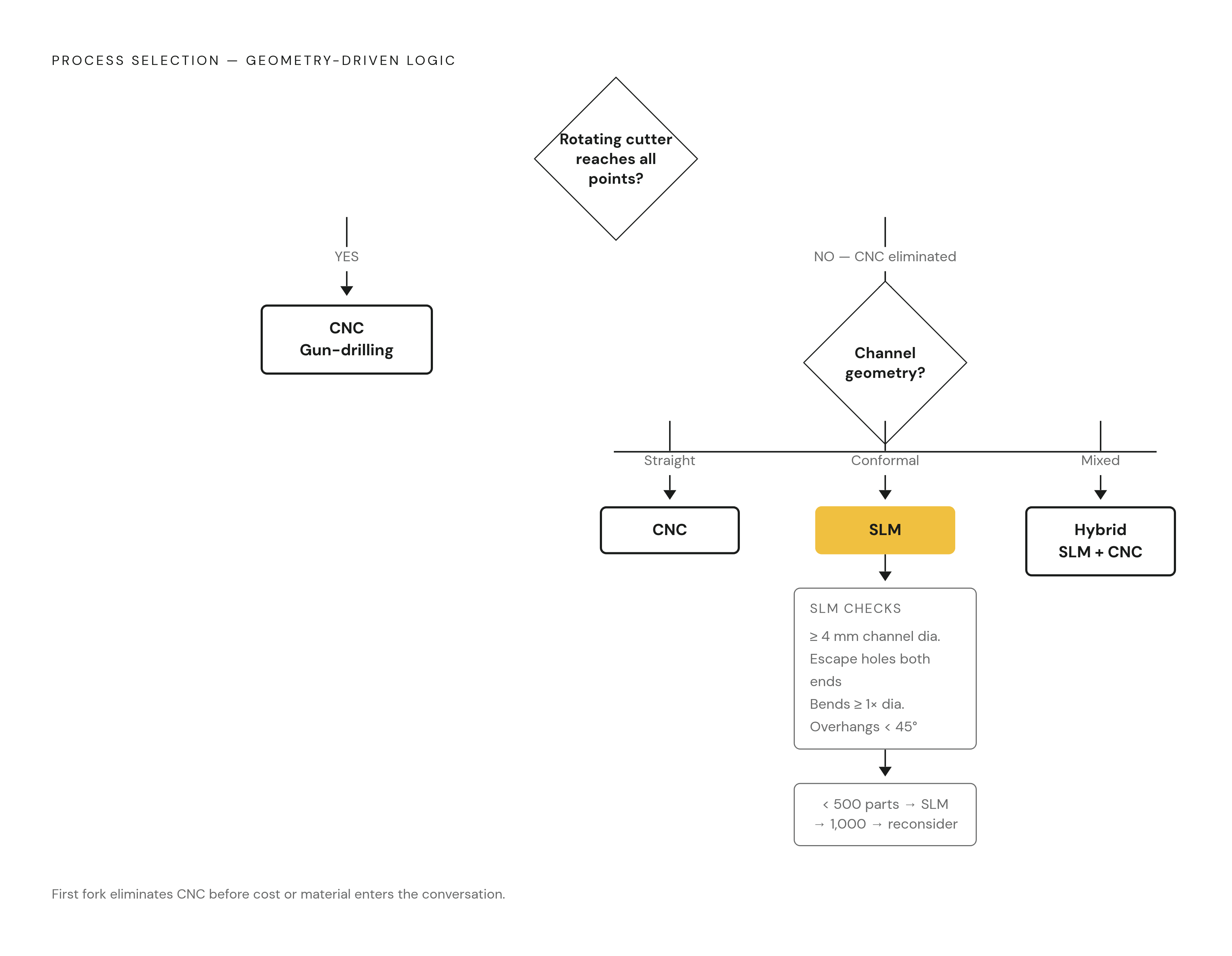
Start with tool access. Can a rotating cutter reach every point inside the channel from at least one external face, with nothing blocking the path? If the answer is no, CNC is out, and nothing about cost or material changes that verdict.
From there, classify the geometry. Straight, accessible, non-intersecting channels point to CNC gun-drilling, the fastest and cheapest option when it applies. Conformal, curved, or branching geometry points to SLM, and from there straight into SLM's design rules. Mixed cases, where the outer surfaces need tight tolerances but the internal channels are complex, point to a hybrid build, with orientation planned around both depowdering and CNC fixturing from day one.
If the path leads to SLM, run the feasibility checks: channel diameter at 4 mm minimum for reliable depowdering, escape holes of at least 3 mm at both ends of every enclosed passage, no bend tighter than one channel diameter, no blind dead ends, internal overhangs kept above 45° from horizontal wherever possible, and build orientation chosen to minimize down-facing surfaces and support intrusion inside the passages themselves.
Material selection follows the environment: corrosive, high-temperature, or structural weight-driven, matched against the alloy guidance above.
Then check volume. Below roughly 500 complex parts, SLM economics tend to favor the process. Approaching 1,000 units, it's worth asking whether simplifying the geometry could unlock CNC at a lower cost for that production run.
Last, run a process-lock audit. If the channel geometry only exists because of SLM, write that dependency down explicitly. A future production volume that demands casting or high-speed CNC will require a redesign, and planning for that now costs a lot less than discovering it after the tooling money is spent.
Geometry sets the boundary first, full stop. Cost, material, and volume only operate inside the space that geometry has already defined, never before it.