Multi-Process BOM Lead Time Optimization for Prototype Builds
Consolidating fragmented vendor sourcing collapses delays that compound between processes.
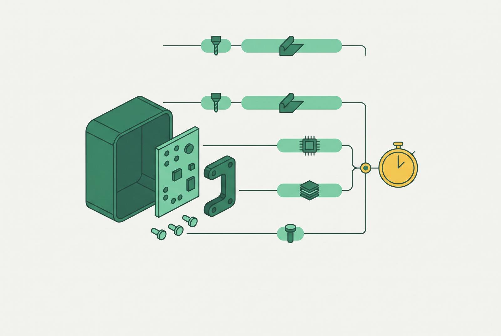
A multi-process mechanical assembly sourcing platform should give one quote and plan how work such as machining, welding, and finishing fits together. For prototype builds, its value is reducing the gaps between processes. Multi-process BOM lead time optimization therefore starts with mapping dependencies, resolving manufacturing questions early, and consolidating work where one capable partner can manage the full chain.
Why prototype schedules slip between processes, not within them
Every vendor has been tracked, the parts all look on schedule, and somehow the prototype is still late. The missing time sits between those updates. CNC machining, sheet metal fabrication, spring manufacturing, gasket cutting, tube bending, and finishing each have their own queue, capacity, and design for manufacturability requirements. When sourced separately, each also has its own RFQ cycle, engineering exchanges, and shipping leg. A shop can meet its quoted manufacturing time while the assembly misses its date.
Those independent clocks never synchronize by default. A one-day slip in one process delays the next process, which delays the one after it. The schedule loss compounds even when no single delay looks serious enough to escalate. This is a structural feature of fragmented sourcing.
Promwad's NPI analysis identifies late hardware revisions, component availability problems after design freeze, incomplete documentation during EMS onboarding, and test coverage gaps as common delay sources. Each exposes a decision that failed to cross a phase boundary in time. The same problem appears within a mechanical BOM when a part is considered complete by one shop but is not ready for the next.
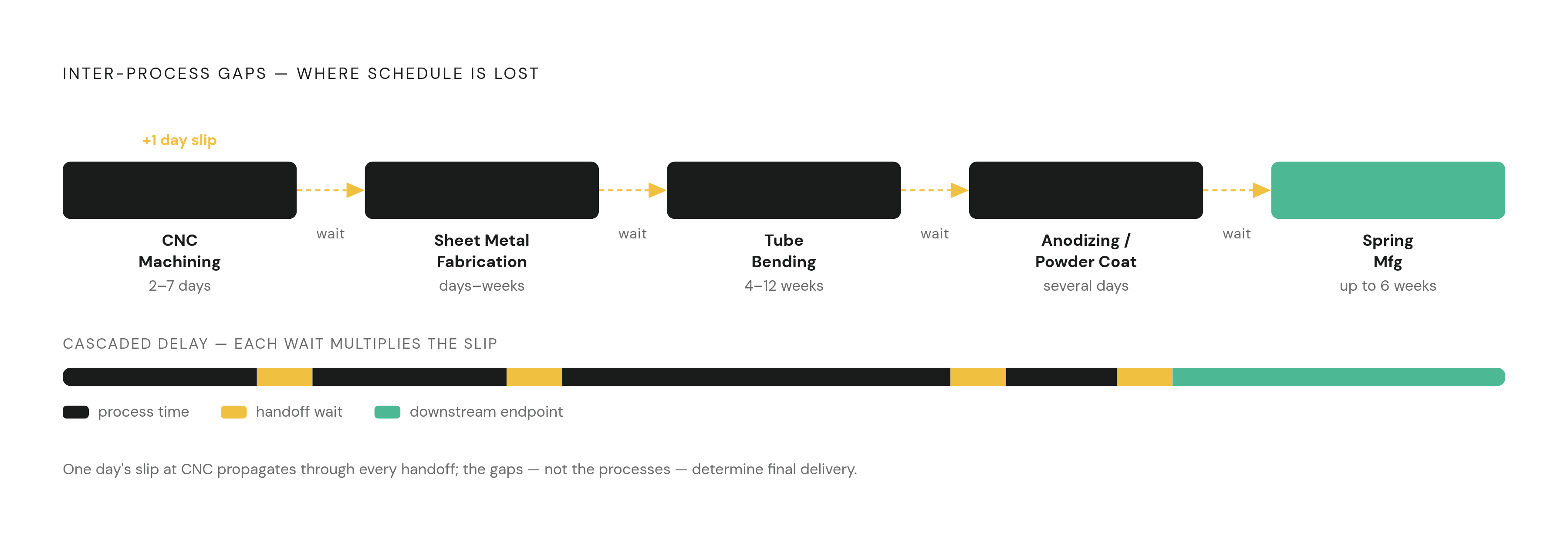
How a multi-process mechanical BOM creates compounding sequential risk
A mechanical BOM is a dependency graph. A bent tube feeds a weldment, a spring feeds a subassembly, and a machined housing receives a gasket. The downstream operation cannot start until the required upstream part arrives and is inspected. More parts and more process types create more opportunities for one late node to hold up the chain.
The timing differences can be large. Small-quantity CNC prototypes take 2–7 working days, while anodizing or powder coating adds several days afterward. Sheet metal prototypes can take days, but thick or hard alloys need slower bending and more passes through the press brake. A dieless knife-cut gasket made from customer CAD can take under 24 hours, while conventional gasket processes with approved drawings average 2–3 weeks.
Other branches run on much longer clocks. Western Spring Manufacturing says that complex precision work that needs specialty wire, new tooling, and documented finishing can take six weeks or longer. Standard custom tube bending runs 4–12 weeks from RFQ to delivery, before allowances for specialty materials or unique tooling. These ranges make the average part lead time a poor planning measure. The governing path is the connected sequence that takes longest to reach assembly.
Why fragmented vendor sourcing multiplies inter-process gap risk
Separate sourcing adds more than freight and receiving work. Every vendor has its own RFQ cycle, place in the queue, and way that work can fail. Each shop reviews its own portion of the BOM, so a cross-process incompatibility can remain unresolved even after every individual part has received a manufacturability review. Local approval is not whole-assembly approval.
When part numbers, package codes, or tolerance requirements are missing, each vendor has to ask its own questions. Meanwhile, independent deliveries create stalls when one part arrives without the part it depends on. If a supplier loses capacity, switching means re-quoting and re-approving work rather than simply moving the same start date to another shop.
Quote response time offers an early warning. A supplier that takes two weeks to return a quote signals an operational capacity or discipline problem that may recur when production questions arise. Yet a broken promise or a vendor that goes silent can go unnoticed until delivery day. With five vendors, there are more opportunities for at least one commitment to fail than with one. The engineer may keep the master schedule up to date, but none of the separate suppliers can see or control all of it.
Identifying the longest-pole process before the schedule is locked
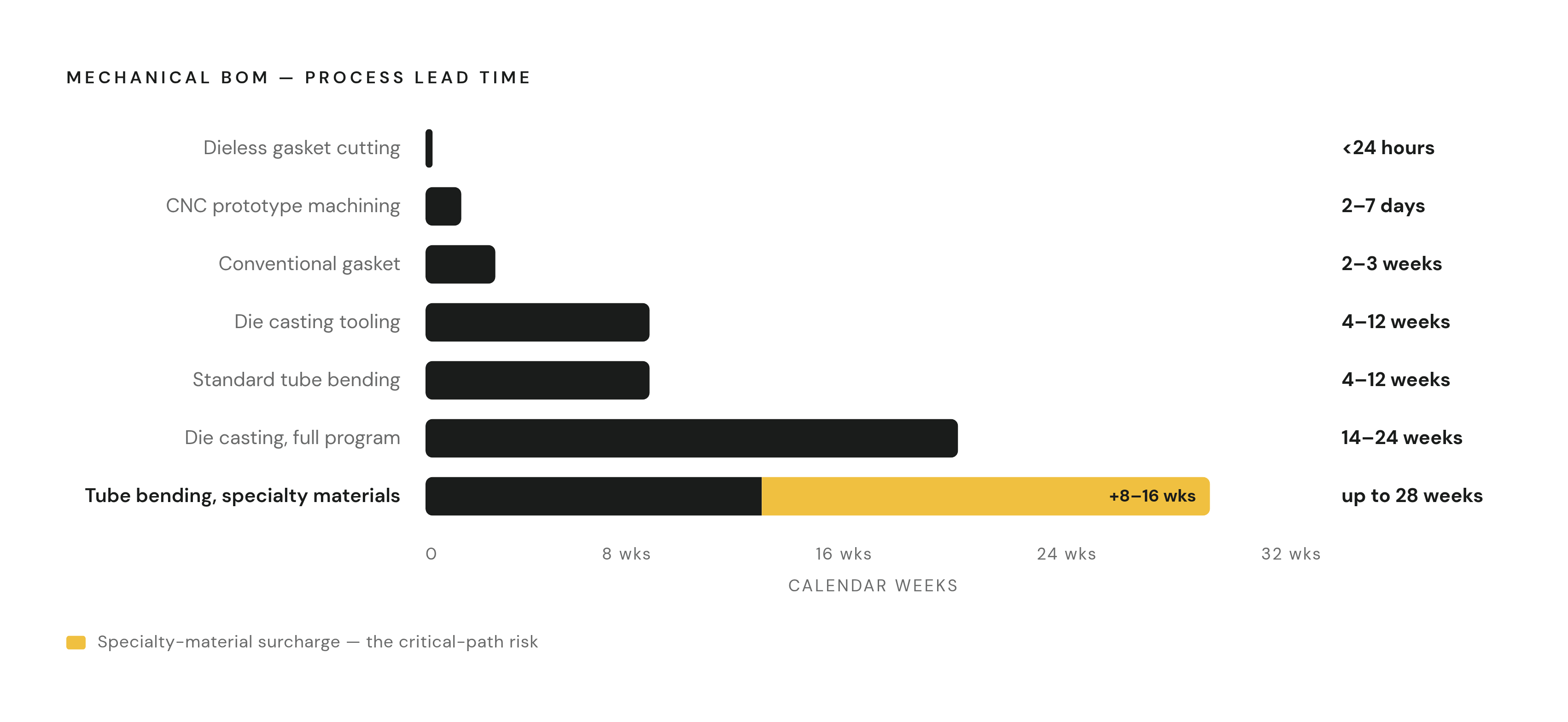
The first practical step is to rank every BOM line by process lead time and material availability before sending RFQs. The three longest poles should receive DFM review and RFQ release first, even when other parts feel more design-complete. This is critical-path analysis. The purpose is to find the process that governs assembly readiness before a delivery date becomes a commitment.
Tube bending deserves immediate attention when it appears on the BOM. On top of the standard lead time for tube bending, specialty materials add 8–16 weeks and unique tooling adds 4–6 weeks. A mid-cycle engineering change can trigger another 8–16 weeks of specialty material sourcing. Sending that RFQ two weeks late with unresolved geometry can therefore consume a 12-week schedule before the remaining processes become relevant.
Springs can govern an independent assembly branch, while finishing adds time after machining or fabrication is already complete. That position makes finishing easy to underestimate. DFM must first settle the manufacturing process and then verify the design against its constraints. It may take hours to settle a question before RFQ, but the same question raised after tooling or material has been committed can cost weeks or, for tube bending, months.
Front-loading DFM to collapse the review cycles that eat inter-process time
Most lost handoff time is iteration time. A manufacturability problem becomes visible after parts arrive, the design is revised, and the work goes back into a queue. To avoid that sequence, early DFM should look at production constraints that affect how the part works, how complex it is, and what the next process needs. It is a way to catch decisions that take weeks to undo.
Process selection comes before detailed geometry review. Aluminum components have an economic and timeline crossover between CNC machining and die casting at moderate volumes. Below that threshold, CNC is more economical and arrives quickly, while die casting requires 4–12 weeks for tooling alone and 14–24 weeks for a full new program. Even simple single-cavity tools take 4–6 weeks. That difference belongs in the prototype decision, rather than becoming a surprise when the production process is reconsidered.
Once the process is chosen, the review should check constraints such as springback in thick sheet metal and geometry questions in tube bending. DFM feedback built into quoting can compress review cycles from days to hours, rather than making a completed quote the start of another engineering engagement. Part consolidation can remove handoffs altogether by reducing the number of parts that must converge. Approved alternatives also deserve attention during this review when a component has long lead times, limited availability, or only one viable supplier.
Building a complete RFQ package that eliminates quote-cycle gaps
A complete RFQ package closes the information gap between design completion and manufacturing start. A 3D model rarely gives a shop everything it needs. Function, tolerances, finish, quantities, and project priorities determine how the part should be made and quoted. Each omission invites another exchange before the work can enter the queue.
The package should include native CAD or STEP files and a controlled 2D drawing with its revision level. It should give the units, the material standard, the material certifications needed, and the quantity breaks. Surface finish, heat treatment, coating specifications, and machining allowance where applicable also belong in the release. Packaging and inspection requirements define what counts as a usable delivery. A clear target lead time lets the supplier flag when it lacks capacity before it starts planning production.
For a multi-process BOM, those documents should be in one package that covers all the processes needed. That gives reviews a shared starting point instead of allowing clarification cycles to unfold in series. Incomplete part numbers, missing package codes, and obsolete references should be resolved before release because the same ambiguity can stall several suppliers at once. This is a gap the engineering team can close directly. A fast quote has little schedule value if unanswered questions still separate it from manufacturing start.
How can one vendor quote and coordinate machining, welding, and finishing?
A capable multi-process sourcing partner needs visibility across the full BOM. Such a partner can provide a single RFQ response, purchase order, and shipment while managing the process dependencies internally. When separate quotes are collected, each shop still runs on its own production clock.
With that visibility, DFM can address the whole assembly. Independent parts can be queued in parallel, while connected operations can be staged in dependency order. If material arrives early or one process finishes ahead of plan, the next operation can benefit without another vendor handoff. A machined housing and its custom gasket, or a tube-bent frame and its weldment, can be planned against each other.
Vertical integration removes physical transfers as well. In spring manufacturing, moving between suppliers for sequential heat treatment and finishing adds logistics and re-qualification delay without adding manufacturing value. Doing those stages under one roof removes the delay between vendors. Where no fully integrated shop covers the BOM, comparing quotes from 3–5 verified factories with open capacity at the time of enquiry can identify the supplier best positioned to absorb the work. Compare process coverage, cross-process DFM, current capacity, and delivery documentation.
Sequencing and parallel-tracking the BOM to recover schedule even with multiple vendors
When consolidation is not possible, the next step is to distinguish true dependencies from independent parts that merely converge at assembly. Sequential operations should start as early as possible, in dependency order, with DFM resolved before RFQ. Independent processes should be released together so their clocks run concurrently. They are different scheduling problems and should not share a default sequential release pattern.
Tube bending and gasket cutting make the distinction clear. If neither requires the other's output, the gasket RFQ need not wait for the tube-bending cycle to finish. Complex springs and standard CNC parts can likewise run in parallel when their dependencies allow it. Less-finalized parts can enter parallel release only with explicit interface definitions. Dimensions, connection points, and tolerances must be agreed so that time saved during sourcing does not become a fit problem at assembly.
Comparing several verified factories that have open capacity can shorten the wait between RFQ release and the start of manufacturing. Surface treatments need their own planned lead times after machining or fabrication. Parts requiring the same treatment should be batched into a single release after they are complete. That shared release must be reflected in the upstream schedule, so the last machined piece does not become an unplanned hold on the treatment run.
What a well-sequenced multi-process BOM release actually looks like in practice
In a well-sequenced release, a tube-bent frame feeding a weldment appears as a connected path, while a machined housing and custom gasket appear as parts converging at assembly. The longest processes receive DFM attention first. Their geometry, material, and tooling questions are resolved before RFQ release, while the remaining BOM is prepared for parallel work. Each release includes CAD, controlled drawings, material and finish specifications, inspection requirements, and the target lead time. The schedule starts from dependencies.
At release, independent branches begin together with their interfaces agreed. The frame's downstream welding remains tied to the bent part's readiness, while surface-treated components converge at a planned treatment release. With a capable multi-process partner, that mapping, review, and release planning can become one quoting and production-planning conversation. Across separate vendors, the same dependencies must remain explicit.
Dimensional documentation then closes the handoff at delivery. It is not paperwork added after the useful work. A part with documentation can move into the next process without another wait for inspection, while a part waiting for incoming inspection holds up the chain. From the engineer's perspective, control means knowing not only when each shop will finish, but what must be resolved, delivered, and accepted before the next operation can begin.