Printed Core and CNC Shell Hybrid Parts for Internal Geometry
Combining printing for unreachable internal features with CNC machining for precision surfaces.
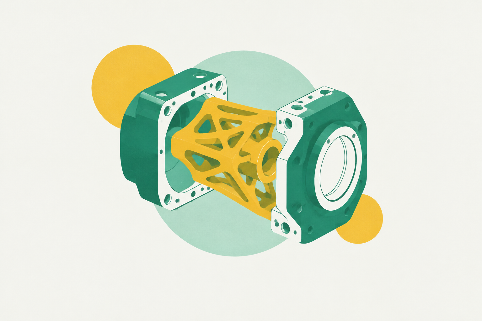
Printing makes internal geometry that a cutting tool cannot reach, while CNC finishing gives critical surfaces the fit and finish they need. For sourcing, a multi-process mechanical assembly sourcing platform needs to quote the printed preform, machining, and assembly operations in one workflow, using a digital package that makes that division explicit.
Why neither pure additive nor pure subtractive manufacturing can fully serve complex internal geometry
A cutting tool needs access to the surface it cuts. Printing can build internal channels, lattices, and undercuts, while topology-optimized structures put material where the load demands it. FDM at 0.2 mm layer height produces vertical-wall roughness of Ra 12–25 µm, while DMLS metal prints land at Ra 10–15 µm, requiring finish machining on functional surfaces.
CNC machining routinely delivers Ra below 1 µm and dimensional tolerances of ±0.005 mm. Access remains its hard limit. Internal undercuts and conformal cooling paths can demand split assemblies or another process. Cutting complex parts from billet also turns much of the starting material into chips, which costs more when high-value alloys are used. Engineers must therefore locate the boundary between geometry that must be built and surfaces that must be cut.
Two distinct hybrid workflows and which part families each suits
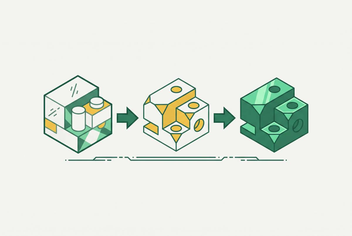
Sequential hybrid manufacturing prints a near-net shape, then moves it to a CNC machine for finishing. Bearing seats, mating flanges, threaded features, and tight-tolerance bores are machined after the build. This route uses standard CNC equipment and slicing software, so shops can use familiar ways of working and spend less on equipment. Structural brackets, housings, mould inserts with conformal cooling, and medical fixtures suit this route when every precision surface remains reachable.
Integrated hybrid manufacturing alternates additive deposition and machining in a single machine. A tool can finish an internal bore, sealing groove, or channel interface before later layers enclose it. This route is harder to execute in practice. Additive and subtractive toolpaths must be sequenced in a unified CAM environment.
For engineers choosing the route, the first test is whether every surface needing CNC precision remains accessible after the build. If it does, sequential hybrid fits the access requirement. If a precision surface becomes enclosed, the choice is integrated hybrid or a design change that relocates that feature. Volume adds a separate constraint to that decision. When print-then-machine cycle time becomes limiting, casting-to-CNC is an alternative.
Where to draw the boundary between the print zone and the machine zone
The boundary follows two questions asked of each feature. Can a cutting tool reach it, and does it need sub-1 µm Ra or ±0.005 mm precision? Those values give a basis for comparison, but the requirements on the feature’s drawing decide where it belongs. Access and function decide the split together. An unreachable channel belongs in the print zone only if its required surface condition can be delivered there, otherwise the workflow or design must change.
Internal channels, conformal cooling paths, lattice infill, and organic load-path geometry belong in the print zone. So does topology-optimized bulk structure where surface finish and dimensional precision are not functional requirements. Bearing seats, seals, mating flanges, precision bores, and threads belong in the machine zone when printed variation would cause failure. A surface that contributes to a tolerance stack-up cannot be assigned to printing simply because it looks easy to build.
Conformal cooling mould inserts show how this works. LPBF creates an H13 tool steel insert with channels following the mould cavity contour, a path that cannot be drilled conventionally. CNC then finishes the parting line, cavity face, and ejector pin bores. Palcam documents ±10 µm tolerances for finish-machined critical surfaces on its inserts. The channels and finished interfaces occupy distinct regions, each assigned to its process from the start.
Antolin et al. demonstrate a related split in a microstructured blisk blade. Laser powder bed fusion creates the heterogeneous internal microstructure, reducing mass compared with a solid counterpart, while 5-axis CNC finishes the aerodynamic surface and attachment interfaces. Here, the exterior is not merely a cover. It has functional surface and tolerance requirements that the internal structure does not share. The example shows why “printed core and CNC shell” describes a division of work with selective machining of outside surfaces.
How to design the print zone to support machining — stock allowance, datums, and fixturing
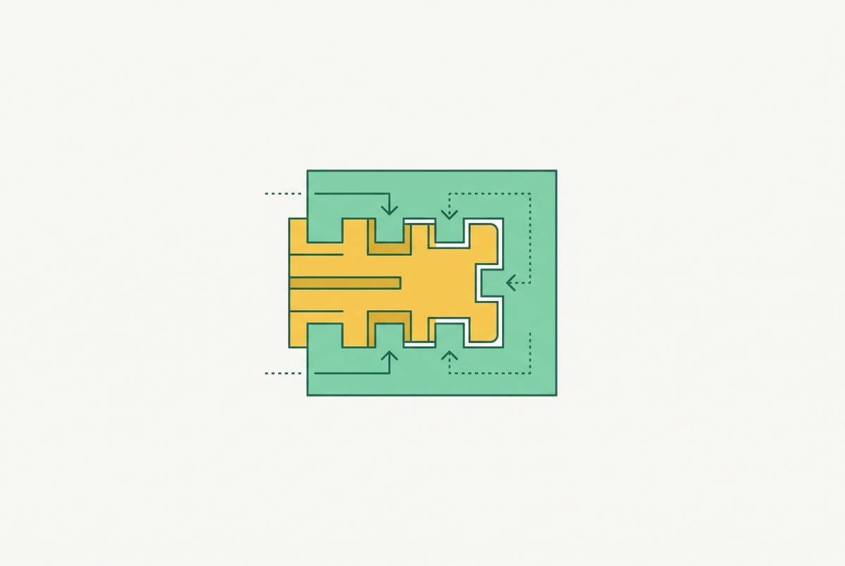
Once the zones are assigned, the design must make finishing possible. For that purpose, leave 0.5–1.5 mm of stock on every surface designated for CNC finish machining. Model this allowance in the print geometry. The design must provide this material before the part reaches the machinist. Insufficient allowance can force cutting into as-printed subsurface porosity or layer boundaries, degrading the surface intended for the finished interface.
Plan machining datums before the part reaches fixturing. Add sacrificial reference pads or bosses with flat, accessible surfaces that can be probed to establish the coordinate system. These features can be removed in a finishing pass. Three-point contact or kinematic locating surfaces built into the print can also eliminate the need for custom soft jaws on every job.
Workholding needs its own space in the model. Organic printed shapes are harder to clamp than rectangular billets, so include at least one flat clamping surface even when it serves no function in the finished part. Integrated equipment avoids re-fixturing for mid-build machining, but removal for external operations reintroduces datum risk. The drawing must also distinguish acceptable as-printed dimensions from dimensions finished to machining tolerance. Without that distinction, a shop may try to print more precisely than the process allows or accept a printed feature that needed cutting.
Material pairing across the two zones and its effect on process sequencing
The print material sets the starting conditions for CNC finishing. It determines the viable additive route and, with that route, the surface condition, thermal history, and dimensional state of the preform. The zones need not use different materials. An aluminum alloy near-net form made by SLM/DMLS can have its bearing interfaces and connector faces finish-machined, while an SS316L DMLS body can retain complex printed geometry around machined precision bores and sealing surfaces. These are process pairings within a part, rather than necessarily separate core and shell components.
LPBF and DMLS builds hold stress from rapid thermal cycling, so removing material before stress relief can cause distortion. H13 conformal cooling inserts make that risk especially relevant because residual stress can move dimensions during machining. For most metal hybrid workflows, the sequence is printing, stress relief through heat treatment, rough CNC, then finish CNC. That intermediate treatment belongs in the lead-time plan before finishing is quoted.
Ti-6Al-4V and nickel superalloys use the printed zone to reduce material waste, with CNC handling functional surfaces. Polymer routes require a different finishing plan. SLS PA12 bodies can have their mating surfaces and precision holes machined, while structural bodies made from PEEK and carbon-filled PEEK can be printed by FDM on heated-chamber platforms and finished with 3-axis CNC. SLA photopolymers pair high-resolution printed geometry with precision grinding or CNC at critical interfaces.
A printed polymer body can receive CNC-machined metal threaded inserts where fastening will be repeated. That changes the sourcing scope from finishing one preform to supplying and assembling distinct components. A printed master pattern can also be used for urethane casting when a small batch needs properties that the print material cannot match.
Fatigue and structural performance differences between additive preform routes, and what they mean for machine zone design
Additive preform routes can reach the same geometric tolerances after machining yet behave differently under repeated load. Benchmarking of aerospace structural preforms found sharply poorer fatigue performance for WAAM and AFSD aluminum parts than for wrought Al 6061 stock, associated with porosity and lower hardness. The caution is specific to the process decision. Machining can correct shape and surface variation without correcting the internal condition that limits fatigue life.
For a fatigue-loaded print zone, preform selection must therefore be a structural engineering decision as well as a cost or schedule choice. Before setting the zone boundary, consider whether fatigue-critical regions should stay printed or move to a machined feature or cast-then-machined sub-element. The geometric framework needs this load-based test before the design is committed to production.
For metal additive preforms, CT scanning or X-ray inspection of the print zone belongs before CNC finishing because internal porosity is not visible on the finished exterior. A failed inspection at that stage still leaves the additive build as sunk cost. That risk reinforces the value of process simulation and build monitoring during printing. Inspection is a required checkpoint in the route.
How do you get a single quote for a hybrid part or complex assembly?
The as-printed model must include machining allowances, datum features, and the geometry needed for workholding, while the final model must be watertight and free of geometry errors. STL alone is not enough for production quoting. It cannot show tolerance intent or how the dimensions of the print and machine zones must relate to each other. The manufacturer needs that relationship to plan the route, fixturing, and inspection as one job.
The drawings supply intent that geometry alone cannot. Critical dimensions, tolerances, GD&T callouts, datum references, surface finish requirements, and machining allowance zones must be explicit. Mark which dimensions are accepted as printed and which apply after machining, and identify the inspection surfaces and applicable standards. Process notes must state the additive process and print material. For metal parts, they must also identify required stress relief or heat treatment between printing and machining, with that sequence agreed before quoting.
An assembly quote also needs the surrounding design context. Provide the bill of materials, mating parts, interface tolerances, and any stack-up analysis that sets the required precision of the machined features. Without those relationships, a supplier sees the shapes of the parts but cannot tell how the assembly must fit together. A sourcing partner with instant DFM feedback can flag too little stock, missing datum features, and problems with material compatibility before manufacturing starts. That feedback is useful only when the submitted package exposes the intended split.
For a multi-process mechanical assembly sourcing platform, the decisive capability is quoting the full bill of materials, printing, machining, and assembly operations in one workflow. A file-upload interface alone does not establish that capability. The value is removing the coordination overhead of separate additive and CNC vendors without hiding the process requirements from either operation. The buyer must check that the quote covers the designed route, including intermediate treatment and inspection, as well as the final shape.