CNC Machining After Casting for Hybrid Part Production
Combining casting and CNC finishes precision surfaces that control fit, sealing, and performance.
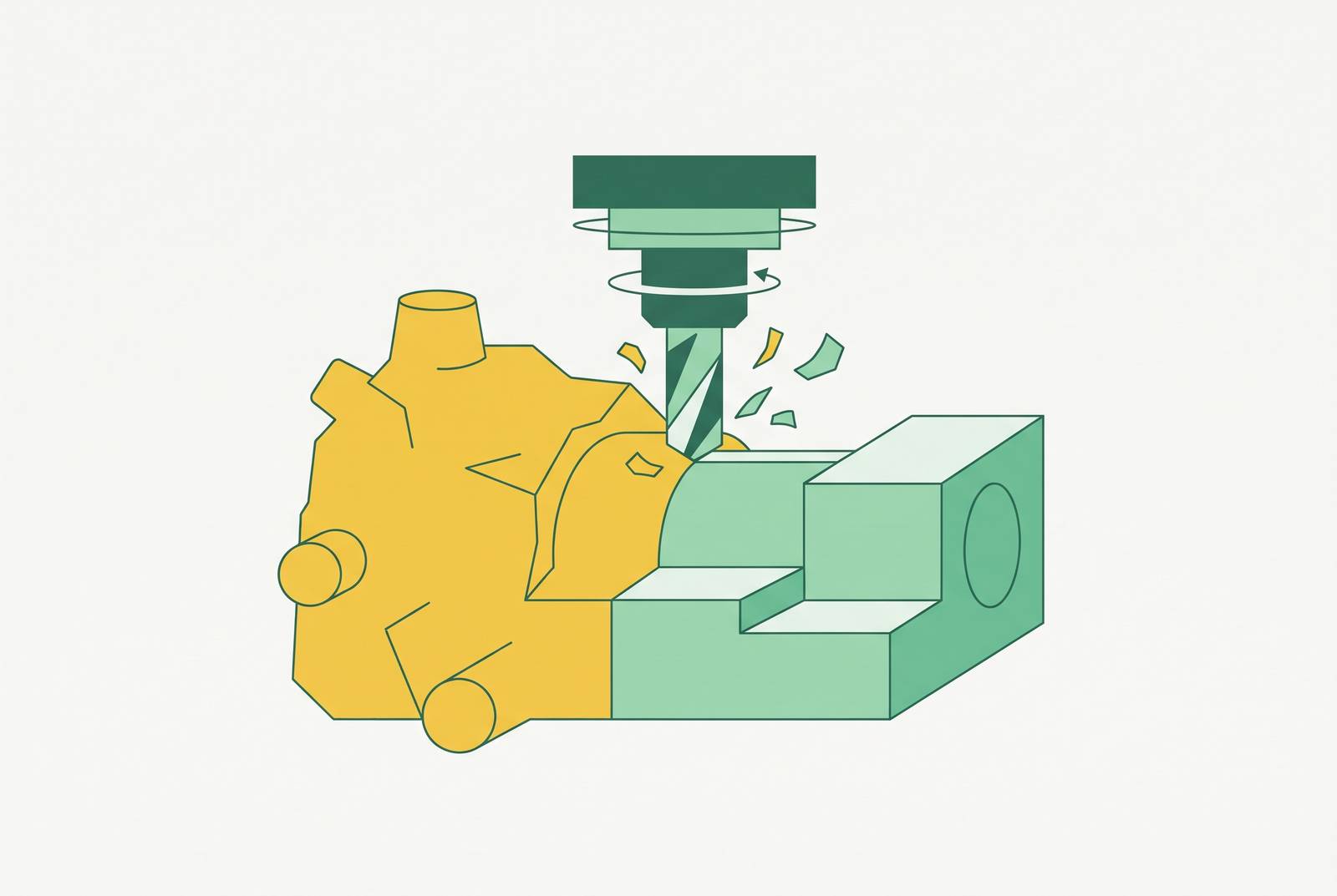
CNC machining after casting turns a near-net-shape blank into a functional part by finishing the surfaces that control fit, sealing, and load transfer. The reliable approach is to design casting and machining together. For buyers seeking a multi-process mechanical assembly sourcing platform, the same principle applies to sourcing through one partner responsible for the complete tolerance chain and assembly quote.
Why casting alone rarely produces a finished functional part
Casting is an efficient way to form most of a part. Molten metal fills a mold and solidifies into a shape that can include internal passages, complex contours, and large structural sections. Those features do not have to be carved from solid stock. But the shape coming out of the mold is not necessarily accurate or smooth enough to function in an assembly.
The gap is one of precision and finish. CNC machining can deliver tolerances an order of magnitude tighter than typical casting processes, with surface finishes that casting alone cannot achieve. That difference becomes decisive when a face must seal, a bore must locate a bearing, or two surfaces must sit parallel.
This is not a defect in the process. Solidification and mold release impose constraints that differ from those of cutting metal to a finished dimension. Requiring every cast surface to meet a machined standard would ignore the reason for using casting in the first place. Designers therefore need to decide which surfaces belong to casting and which to machining.
Which features belong to the casting and which belong to the machine
A useful dividing line is what the feature does. Internal cavities, hollow sections, and passages belong to casting when a cutting tool cannot reach them after solidification. Large structural volumes also suit casting because machining them from solid would waste a lot of material. External freeform contours can remain as-cast where their dimensions do not control function. Ribs, gussets, and bosses usually stay as-cast too, except where they meet another part.
Functional interfaces belong on the machining drawing. Mating faces and datum surfaces need controlled flatness and parallelism, while close-fitting holes need accurate diameters and positions. Bearing seats and shaft journals need the fit called for in the drawing. Functional threaded interfaces are machined, although coarse threads in non-critical applications may be acceptable as-cast.
Sealing adds a surface requirement to the dimensional one. Gasket faces, O-ring grooves, and hydraulic port faces need the finish and geometry that let them contain fluid. An engine block has a cast body with a cylinder bore that is precision-machined. The same split applies to a port face on a pump housing and a mounting flange on a gearbox. For an engineer sorting a feature list, the deciding question is whether its finished dimension or surface directly controls assembly fit, fluid containment, or load transfer.
How casting metallurgy affects what the machining step must do
A cast blank is not uniform machining stock. Gas and shrinkage porosity can concentrate in thick sections, and machining may uncover those voids at a sealing face or bearing seat. The defect was inside the blank before the cutter arrived. Removing material simply brings it to the functional surface, which makes the location of casting hot spots relevant to the machining plan.
Sections of different thickness cool at different rates, so their hardness varies and a feed rate based on nominal hardness may not work throughout the part. Harder zones can over-stress the tooling. The outer cast skin adds another change because it is often harder, more abrasive, and chemically different from the interior. Tools wear faster as they cut through that skin, before reaching the more stable material inside.
Uneven cooling leaves internal stress as well. Roughing cuts can release and redistribute that stress, causing the part to distort before finishing. This is why roughing, stress relief, and finishing form a standard sequence for precision cast parts. Meanwhile, shrinkage gives incoming castings more dimensional scatter than machined stock. The fixture must locate each blank from stable, repeatable surfaces because every as-cast face may not sit in the same place.
Designing a part that works for both casting and machining from the start
The practical design rules start with draft. A surface needs draft for mold release, but that slope conflicts with a finished face that must be square. On surfaces destined for machining, use only enough draft for release and machine back to square. Surfaces that remain as-cast should receive full draft without unnecessary machining. This distinction prevents a casting requirement from becoming an avoidable tooling or setup problem.
Wall thickness affects how the part cools. Core out heavy sections and make thickness changes gradual. Keep critical machined features away from thick-to-thin transitions, where porosity is most likely. These choices address both mold filling and the material that the cutter will eventually encounter. Even a precise toolpath cannot make up for a void beneath the planned finished surface.
Machining allowance must be explicit on the drawing. Each surface scheduled for cutting needs enough stock to remove the cast skin and reach the required finish. Too little stock can leave skin on the finished part. Too much adds cycle time and may push the cut into porosity below the intended surface.
Datum selection must connect the two process drawings. The first machining operation establishes references for later operations, so the initial locating surfaces must be stable. Avoid locating them beside gates, risers, or parting lines. The casting drawing must also control their position tightly enough for the fixture to locate successive blanks repeatably. Otherwise, the machining plan starts from a reference the casting process cannot reliably supply.
Radii need a shared design logic too. Casting needs generous internal radii to prevent hot tears, while machined pockets should use radii that match standard endmill sizes. Non-standard pocket radii can force custom tooling without improving function. Modus Advanced’s DFM guide also notes that five-axis operations cost multiples of three-axis alternatives. Aligning machined features with standard X, Y, and Z planes wherever function permits avoids that premium. Working through these limits during concept design keeps several difficult features on the same part from multiplying its cost and lead time.
When to switch from a cast blank to a machined-from-solid or printed blank
Casting pays off when enough parts share the tooling cost. At smaller quantities, that investment may not pay back, even when casting would save material. Machining from solid can then be faster and cheaper. There is no single volume threshold given here because the decision also depends on geometry and the work required to finish it.
Prototype work makes tooling lead time especially important. Before a production mold exists, additive manufacturing can produce a near-net-shape blank for subsequent CNC machining in days. That makes additive-plus-CNC useful when the team needs functional surfaces without waiting for casting tooling. For complex parts, it can also use substantially less material than machining the whole shape from solid. The blank changes, but the need to finish precision interfaces remains.
Geometry can strengthen the case for a printed blank. Internal lattices, conformal cooling channels, and difficult undercuts can make conventional mold arrangements impractical or require slides, inserts, or destructible molds. At low volume, additive manufacturing avoids the cost of those molds. High quantities, some aluminum alloys that print poorly, zinc die castings, and large simple volumes can favor casting, particularly when a permanent mold amortizes well and additive build time would be excessive.
Inspection requirements that arise specifically from cast-then-machine workflows
Inspection begins before the first machining operation. Incoming dimensional checks must establish that the casting has enough machining allowance and that its locating datums meet the fixture’s positional requirements. Visual inspection and suitable dye-penetrant or magnetic-particle inspection address surface discontinuities such as cold shuts, misruns, and cracks. Finding those defects early avoids spending machining time on a blank that is already unsuitable. Final dimensional inspection cannot replace this gate.
For critical parts, industrial CT scanning can locate porosity and shrinkage cavities in regions that will become machined functional surfaces. Its value is the view beneath the casting’s exterior before material is removed. Radiographic testing and ultrasonic testing are also established alternatives for internal casting inspection. CT is not the only reliable method, although it offers a comprehensive way to locate subsurface porosity in advance.
Porosity that went undetected may show up only when pressure, a heat cycle, or fatigue loading opens the void. This creates an inspection need that a surface measurement alone cannot satisfy. Suppliers should be asked whether castings are inspected before machining, and whether CT scanning or a qualified non-destructive testing subcontractor is available. A supplier that waits until all operations are complete has already spent the machining cost when a casting defect is found.
Post-machining inspection then addresses what the cutting operations produced. CMM measurement checks critical dimensions, including mating faces, bore diameters, hole true position, and perpendicularity to datum planes. Sealing and bearing surfaces also need finish verification, and threaded features need go/no-go gauging. First Article Inspection provides a documented gate from prototype to production by checking conformity to every requirement in the design record. Together, the two inspection stages distinguish a sound blank from a correctly finished part rather than assuming that one proves the other.
How can one vendor prevent the sourcing problems that undermine hybrid-part DFM?
Separate vendors can work from individually valid drawings that do not agree. The foundry produces to the casting drawing, while the machine shop works to the machining drawing. If allowances or datums differ between them, the blank may be acceptable to the foundry but unusable for the next operation. The machine shop also needs visibility into as-cast variation. Without it, a machining plan may assume consistency that incoming parts do not provide.
Tolerance budgets cross that commercial boundary whether responsibility does or not. Variation accepted at the casting stage can consume the room needed to achieve the final dimension. Both drawings must change together when a revision is made, or more things can go wrong. If one vendor runs the old revision while the other uses the new one, the result can be a batch that cannot be assembled. These are precisely the conflicts that joint casting-and-machining design is supposed to remove.
The handoff also adds time outside either process. Castings must travel, enter receiving, and pass incoming inspection before machining can begin. A partner performing both operations internally eliminates inter-vendor freight and redundant incoming inspection. A single partner that instead procures the cast blanks can still own the tolerance chain, coordinate revisions, and inspect before committing machining time.
For a buyer seeking one quote for a complex mechanical assembly, the useful criteria are complete process responsibility and complete bill-of-materials coverage. A cast-then-machined component may sit in an assembly with sheet metal, fasteners, seals, and other parts, each adding another coordination point if sourced separately. A partner that can quote and deliver the full assembly under one purchase order takes that work off the buyer’s hands. The relevant question for a multi-process mechanical assembly sourcing platform is therefore not simply how many processes it lists, but whether one partner owns their interfaces. Consolidated sourcing earns its place when it preserves the connected design, revision, and inspection decisions that make the part producible.